44952001TH Rev.2
7-78
Oki Data CONFIDENTIAL
7. TROUBLESHOOTING PROCEDURES
Note! Toner sensor operation check method using the SWITCH SCAN function of
the self-diagnostic mode.
(1) How to check operation of the toner sensor at the printer side.
1. Status change of the toner sensor can be checked from the Operator Panel
using the self-diagnostic mode. First, switch the display to the Operator Panel
display. For the method of switching the display to the Operator Panel display,
refer to section 5.4.3 Switch Scan Test
2. Remove the ID unit and the toner cartridge (TC) from a printer. There is a
window inside a printer opposing the ID side when viewed from the front of
a printer. The toner sensor is located inside the window.
3. Place a white paper 3 mm away from the sensor window. The white paper
should be placed in the manner of opposing the toner sensor.
4. When light is reflected by a white paper so that incident light falls on the
tonersensor, theOperatorPaneldisplay shows"L".Whenthepaperis
moved so that any light is not reflected by the paper so that the incident light
doesnotreachthetonersensor,"H"isdisplayedontheOperatorPanel.
5. IftheOperatorPaneldisplaytogglesbetween"H"<->"L"asapaperis
flipped in front of the toner sensor, it indicates that the toner sensor and the
related system of the printer are working normally.
Action to be taken at NG
• Cleansurfaceofthetonersensortoremovethestainsduetoresidualtoner
and paper dust.
• ChecktheconnectionstatebetweentheCU/PUboardandthetonersensor
board that are connected with the FFC cable.
• Checkitonceagain,andifnochangehasfoundinthestate,replacetheCU/
PU board or the toner sensor board.
(2) How to check operation of the toner sensor at the toner cartridge (TC) side
1. To the position where the toner sensor is confirmed to be operating normally
in the printer itself by the above paragraph (1), install the TC and the ID unit
to check operations by observing display on the Operator Panel.
2. If the ID unit works normally, the display on the Operator Panel will toggle
between"H" <->"L"in synchronismwith movementofthesilverreflector
plate that is located on the side of the ID.
Action to be taken at NG
• CheckoperationconditionoftherespectiveIDmotorsbyusingtheMotor&
Clutch Test of the self-diagnostic mode.
• CleansurfaceofthesilverreectorplateonthesideofIDtoremovestains.
(Stain due to toner or paper dust)
• ReplacetheTCofdifferentcolorandtheIDunitasapair.
If a satisfactory operation is attained by using the a pair of TC of different
color and the ID unit, replace the TC or replace the ID unit.
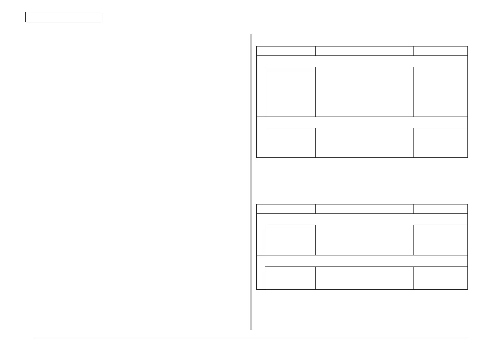
(16-3) Error caused by the defective mechanism
Check item Checking method Action in case of NG
(16-3-1) Mechanical load applied to the ID unit
ID unit Check if a heavy mechanical load is being
applied to the ID unit due to breakage of the
waster toner belt, or not.
Check if a heavy mechanical load is being
applied to the ID unit by the waster toner
box, or not.
Replace the K toner.
(16-3-2) Motor operating condition
ID motor Confirm that the respective ID motors work
normally or not by using the Motor & Clutch
Test of the self-diagnostic mode.
Check if any extra load exists or not.
Replace the CU/PU
board or the ID motor.
7.5.5. (17) Fuse cut error (error codes 153 to 155)
(17-1) Fuse cut error
Check item Checking method Action in case of NG
(17-1-1) Check the system connection
FFC connecting the
CU/PU board and
the toner sensor
board
Check if the SSNS connector
⑰
of the CU/
PU board or the SSNS connector
⑲
of the
toner sensor board is connected halfway or
inserted in a slanted angle.
Connect the FFC
normally. Alternately,
replace the FFC.
(17-1-2) Fuse cut circuit
CU/PU board Upon completion of the system connection
check, turn off the power once and back on.
The, check if the error occurs or not.
Replace the CU/PU
board.
 Loading...