44952001TH Rev.2
4-7
Oki Data CONFIDENTIAL
4.REPLACEMENT OF PARTS
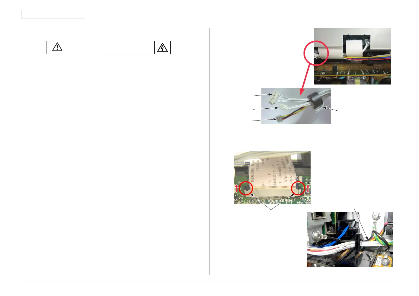
Note! When you remove a FFC cable, refer to the figure of the below.
Refer to the figure of the below for the position of FG-cable.
4.2.5 CU/PU board and low-voltage power supply
Electricshockhazard
When replacing the low-voltage power supply, electric shock may occur. Wear insulated
gloves, or be careful not to touch the conductors or terminals of the power supply directly.
After the AC cord is unplugged, the capacitor may take about one minute to discharge
completely or, due to PCB breakdown, could not discharge. Use caution about electric shock.
[ MC332/MC342/MC352/MC362/MC562 ]
(1) Remove the right side cover. (See 4.2.4)
(2) Remove the three screws (Silver-Colored)
①
and one screw (black-colored)
②
.
(3) Remove the five (silver-colored) screws
③
and unlatch and remove the plate shield
assembly
④
.
(4) Remove all the CU/PU board cables (
⑧
etc.).
(5) Remove the three (silver-colored) screws
⑨
to detach the CU/PU board
⑩
.
(6) Remove all the low-voltage power supply cables.
(7) Remove the two (silver-colored L=8mm) screws
⑪,
and detach the low-voltage
power supply
⑫
, FG-cable
⑬
.
[ MC342dw/MC362w/MC562dw: Wireless-LAN Specifications ]
(1) Remove the right side cover. (See 4.2.4)
(2) Disconnect the Film-LAN-Cable
⑮
and then the LAN cable
⑯
.
(3) Remove the six (silver-colored) screws
③
and unlatch and remove the plate shield
assembly
④
.
(4) Disconnect the USB cable connector
⑰
from the CU/PU board connector.
(5) Remove the two (silver-colored) screws
⑱
. Detach the Wireless-LAN board
⑲
and
the Holder-PCB
⑳
.
(6) Disengage the latches of the Holder-PCB
⑳
and detach the Wireless-LAN board
⑲
.
(7) Remove all the CU/PU board cables (
⑧
etc.).
(8) Remove the three (silver-colored) screws
⑨
to detach the CU/PU board
⑩
.
(9) Remove all the low-voltage power supply cables.
(10) Remove the two (silver-colored L=8mm) screws
⑪,
and detach the low-voltage
power supply
⑫
, FG-cable
⑬
.
Exit connector
Fuser connector
Rear fan connector
Exit cable wound one
turn around core
Method of removing FFC cable
The A section is shifted in the
direction of an arrow.
A
FG cable position
⑬
FG cable
 Loading...