87
HIGH-SPEED COUNTER PV READ: PRV(881) Section 5-2
Applicable Program Areas
Flags
Examples
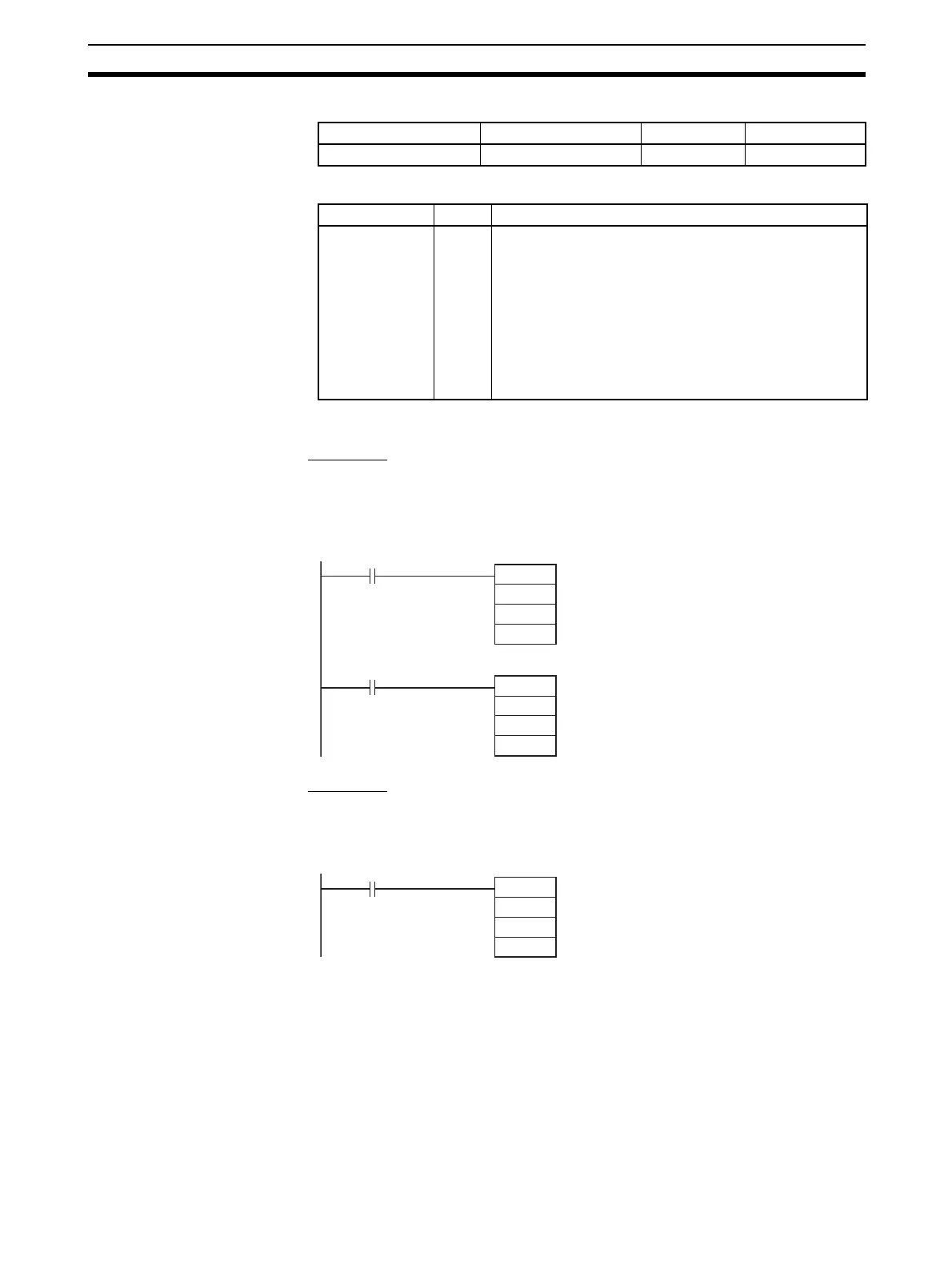
■ Example 1
When CIO 000000 turns ON in the following programming example,
CTBL(882) registers a range comparison table for high-speed counter 0 and
starts comparison. When CIO 000001 turns ON, PRV(881) reads the range
comparison results at that time and stores them in CIO 0100.
■ Example 2
When CIO 000100 turns ON in the following programming example, PRV(881)
reads the frequency of the pulse being input to high-speed counter 0 at that
time and stores it as a hexadecimal value in D00200 and D00201.
Block program areas Step program areas Subroutines Interrupt tasks
OK OK OK OK
Name Label Operation
Error Flag ER ON if the specified range for P or C is exceeded.
ON if the combination of P and C is not allowed.
ON if reading range comparison results is specified even
though range comparison is not being executed.
ON if reading the output frequency is specified for any-
thing except for high-speed counter 0.
ON if specified for a port not set for a high-speed counter.
ON if executed for a port not set for an interrupt input in
counter mode.
@CTBL
#0000
#0001
D00100
000000
@PRV
#0010
#0002
0100
000001
Range comparison table
registration and comparison star
High-speed counter input 0
Read range comparison results
High-speed counter input 0
PRV
#0010
#0003
D00200
000100
High-speed counter input
Read input frequency