132
Built-in Inputs Section 6-1
Restrictions on High-speed Counter Inputs
• The Phase-Z signal + Software reset method cannot be used when high
speed counters 0/1 are operating in Differential Phase or Pulse + Direc-
tion Input Modes and the origin search function is enabled for pulse out-
put 1. The Phase-Z signal + Software reset method can be used when
high speed counters 0/1 are operating in Incrementing or Up/Down Input
Modes.
• General-purpose inputs 8 and 9 cannot be used when high-speed
counter input 0 is being used. Furthermore, general-purpose input 3,
interrupt input 3, and quick-response input 3 cannot be used if the high-
speed counter 0 reset method is set to Phase-Z signal + Software reset.
General-purpose inputs 6 and 7 cannot be used when high-speed
counter input 1 is being used. Furthermore, general-purpose input 2,
interrupt input 2, and quick-response input 2 cannot be used if the high-
speed counter 0 reset method is set to Phase-Z signal + Software reset.
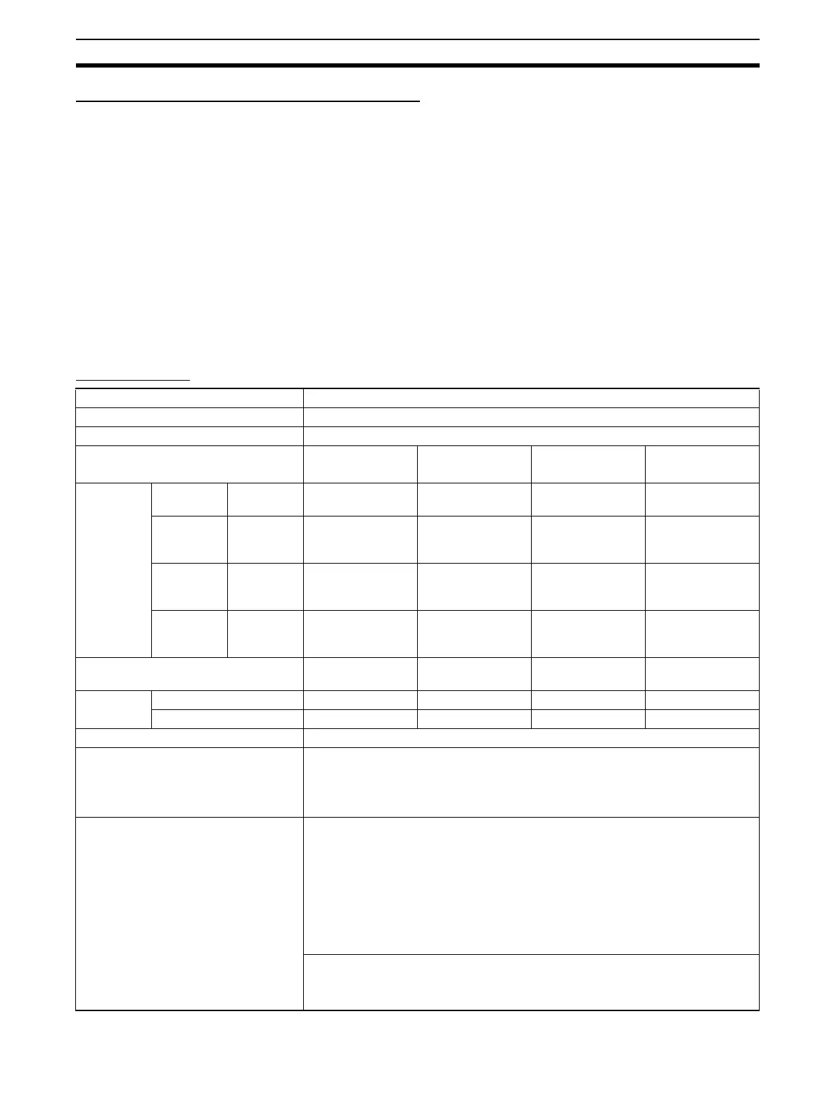
Specifications
Item Specification
Number of high-speed counters 2 (High-speed counters 0 and 1)
Allocated data area CIO 2960 (The bits actually used depend on the pulse input mode selected.)
Pulse input mode
(Selected in the PLC Setup)
Differential phase
inputs
Up/down inputs Pulse + direction
inputs
Increment inputs
Input pin
allocation
High-speed
counter 0
High-speed
counter 1
24 V: 25
LD+: 27
0 V/LD−: 29
24 V: 19
LD+: 21
0 V/LD−: 23
Phase-A input Increment pulse
input
Pulse input Increment pulse
input
24 V: 26
LD+: 28
0 V/LD−: 30
24 V: 20
LD+: 22
0 V/LD−: 24
Phase-B input Decrement pulse
input
Direction input ---
24 V: 8
LD+: 10
0 V/LD−: 12
24 V: 7
LD+: 9
0 V/LD−: 11
Phase-Z input Reset input Reset input Reset input
Input method Differential phase
4X (Fixed)
Single-phase input
+ Direction input
Single-phase input
X 2
Single-phase input
Response
frequency
Line-driver inputs 50 kHz 100 kHz 100 kHz 100 kHz
24-V DC inputs 30 kHz 60 kHz 60 kHz 60 kHz
Counting mode Linear mode or Ring mode (Select in the PLC Setup.)
Count value Linear mode: 80000000 to 7FFFFFFF hex
Ring mode: 00000000 to Ring SV
(The Ring SV is set in the PLC Setup and the setting range is 00000001 to
FFFFFFFF hex.)
High-speed counter PV storage loca-
tions
High-speed counter 0:
A271 (leftmost 4 digits) and A270 (rightmost 4 digits)
High-speed counter 1:
A273 (leftmost 4 digits) and A272 (rightmost 4 digits)
Target value comparison interrupts or range comparison interrupts can be exe-
cuted based on these PVs.
Note The PVs are refreshed in the overseeing processes at the beginning of each cycle.
Use the PRV(881) instruction to read the most recent PVs.
Data format: 8 digit hexadecimal
Range in linear mode: 80000000 to 7FFFFFFF hex
Range in ring mode: 00000000 to Ring SV

 Loading...


