EasyManua.ls Logo

Omron CJ1M-CPU21 User Manual

Omron CJ1M-CPU21
267 pages
To Next Page IconTo Next Page
To Previous Page IconTo Previous Page
Page #169 background imageLoading...
Page #169 background image
140
Built-in Inputs Section 6-1
Procedure
1,2,3... 1. High-speed Counter Enable/Disable Setting (Required)
Set the High-speed Counter 0 Enable/Disable setting to 1 or 2 (use high-
speed counter) in the PLC Setup.
2. Pulse Input Mode Setting (Required)
Set the High-speed Counter 0 Pulse Input Mode in the PLC Setup.
3. Counting Mode Setting (Required)
Set the High-speed Counter 0 Counting Mode in the PLC Setup.
If ring mode counting is selected, set the High-speed Counter 0 Ring
Counter Maximum Value (max. ring count) in the PLC Setup.
4. Reset Method Setting (Required)
Set the High-speed Counter 0 Reset Method in the PLC Setup.
5. Execute PRV2 as described below (required).
Converting the Frequency to a Rotational Speed
Execute PRV2 with the following operands.
C: Control data (Set to #0000 for frequency-rotational speed conversion.)
P: Pulses/rotation (hex)
D: First word for result
Converting the Counter PV to the Total Number of Rotations
Execute PRV2 with the following operands.
C: Control data (Set to #0001 for counter PV-total number of rotations con-
version.)
P: Pulses/rotation (hex)
D: First word for result
Restrictions Pulse frequency conversion is possible only for high-speed counter 0.
6-1-5 Quick-response Inputs
Overview
The quick-response inputs read pulses with an ON time shorter than the cycle
time (as short as 30
µs). Use the quick-response inputs to read signals such
as inputs from a photomicrosensor.
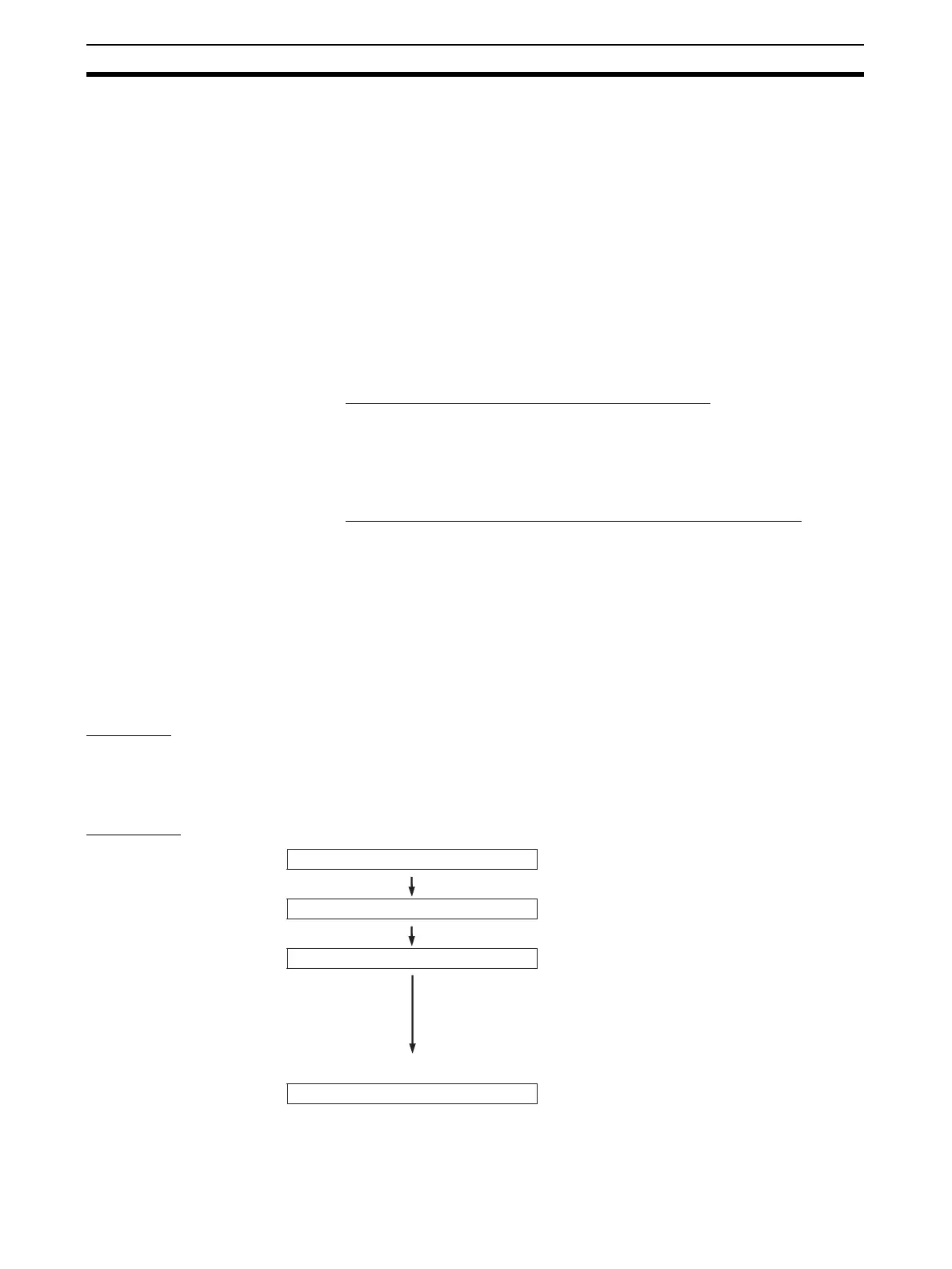
Procedure
Select quick-response inputs.
Wire inputs.
PLC Setup settings
IN0 to IN3 (CIO 2960 bits 00 to 03)
Connect to the selected terminals
between IN0 and IN3.
When IN0 to IN3 are used as quick response inputs,
make the necessary "input operation settings" for
IN0 to IN3 in Programming Console address 60.
IN0: Set the rightmost digit (bits 00 to 03) to 2 Hex.
IN1: Set the second digit (bits 04 to 07) to 2 Hex.
IN2: Set the third digit (bits 08 to 11) to 2 Hex.
IN3: Set the leftmost digit (bits 12 to 15) to 2 Hex.
Use the quick-response inputs in
instructions such as LD.
Ladder program

Table of Contents

Question and Answer IconNeed help?

Do you have a question about the Omron CJ1M-CPU21 and is the answer not in the manual?

Omron CJ1M-CPU21 Specifications

General IconGeneral
CPU TypeCJ1M
Model NumberCJ1M-CPU21
Data Memory Capacity32K words
Operating Voltage24 VDC
Operating Temperature0 to 55 °C
Execution Speed0.1 μs (basic instructions)
Serial CommunicationRS-232C
Expansion CapabilityUp to 3 expansion units
Programming LanguageLadder logic, structured text
Built-in I/O PointsNo built-in I/O

Summary

PRECAUTIONS

1 Intended Audience

Identifies target personnel for the manual, requiring knowledge of electrical and FA systems.

2 General Precautions

Emphasizes operating products as specified and consulting OMRON for critical applications.

3 Safety Precautions

Crucial warnings about PLC operation, memory modification, and handling electrical components to prevent injury.

4 Operating Environment Precautions

Guidelines on avoiding hazardous locations like direct sunlight, extreme temperatures, or corrosive environments.

5 Application Precautions

Precautions for system setup, grounding, power supply handling, and component mounting during operation.

6 Conformance to EC Directives

Details on compliance with EMC and Low Voltage Directives for safe system integration.

SECTION 1 Features

1-1 Features

Overview of CJ1M CPU Units' high-speed, advanced, micro-sized PLCs with built-in I/O.

1-2 Version Upgrades for CJ1M CPU Units

Details on functional improvements from unit version upgrades for CJ1M CPU Units.

1-3 Functions Listed by Purpose

Categorization of built-in I/O functions based on their specific purpose.

SECTION 2 Overview

2-1 Allocations for Built-in CPU Unit Inputs

Mapping of physical inputs to internal addresses and their functional assignments.

2-2 Allocations for Built-in CPU Unit Outputs

Mapping of physical outputs to internal addresses and their functional assignments.

2-3 Allocations for Origin Search Function

Details on I/O points utilized by the origin search function for pulse outputs.

SECTION 3 I/O Specifications and Wiring

3-1 I/O Specifications

Electrical and functional specifications for built-in inputs and outputs, including voltage and current ratings.

3-2 Wiring

Information on connector pin allocations and wiring methods for system connections.

3-3 Wiring Examples

Practical illustrations of various I/O connection configurations for different devices.

SECTION 4 Data Area Allocation and PLC Setup Settings

4-1 Data Area Allocation for Built-in I/O

Allocation of memory words and bits for built-in I/O usage.

4-2 PLC Setup Settings

Configuration parameters within the PLC for managing built-in I/O functionality.

4-3 Auxiliary Area Data Allocation

Allocation of auxiliary area words and bits related to built-in inputs and outputs.

4-4 Flag Operations during Pulse Output

Explanation of how flags change relative to pulse output operations and timing.

SECTION 5 High-speed Counter/Pulse Output Instructions

5-1 MODE CONTROL: INI(880)

Controls operations for high-speed counters and pulse outputs, including starting/stopping and PV changes.

5-2 HIGH-SPEED COUNTER PV READ: PRV(881)

Reads Present Values (PVs) and status information for high-speed counters and pulse outputs.

5-3 COUNTER FREQUENCY CONVERT: PRV2(883)

Converts pulse frequency to rotational speed or total revolutions.

5-4 REGISTER COMPARISON TABLE: CTBL(882)

Registers comparison tables and performs target or range comparisons for high-speed counter PVs.

5-5 SPEED OUTPUT: SPED(885)

Sets output pulse frequency and starts pulse output without acceleration/deceleration.

5-6 SET PULSES: PULS(886)

Sets the number of output pulses for SPED(885) or ACC(888) in independent mode.

5-7 PULSE OUTPUT: PLS2(887)

Outputs specified pulses with acceleration/deceleration, supporting target changes.

5-8 ACCELERATION CONTROL: ACC(888)

Outputs pulses with specified acceleration/deceleration rates, supporting mode changes.

5-9 ORIGIN SEARCH: ORG(889)

Performs origin search or origin return operations using specified methods and parameters.

5-10 PULSE WITH VARIABLE DUTY FACTOR: PWM(891)

Generates PWM pulse outputs with a specified duty factor and frequency.

SECTION 6 Built-in I/O Function Descriptions

6-1 Built-in Inputs

Detailed description of the types, allocations, and specifications of built-in inputs.

6-2 Built-in Outputs

Detailed description of the types, allocations, and specifications of built-in outputs.

6-3 Origin Search and Origin Return Functions

Detailed explanation of origin search and return operations and their parameters.

SECTION 7 Programming Examples

7-1 Built-in Outputs

Practical examples illustrating the programming of built-in output functions.

Related product manuals