EasyManua.ls Logo

Omron CJ1M-CPU21 User Manual

Omron CJ1M-CPU21
267 pages
To Next Page IconTo Next Page
To Previous Page IconTo Previous Page
Page #183 background imageLoading...
Page #183 background image
154
Built-in Outputs Section 6-2
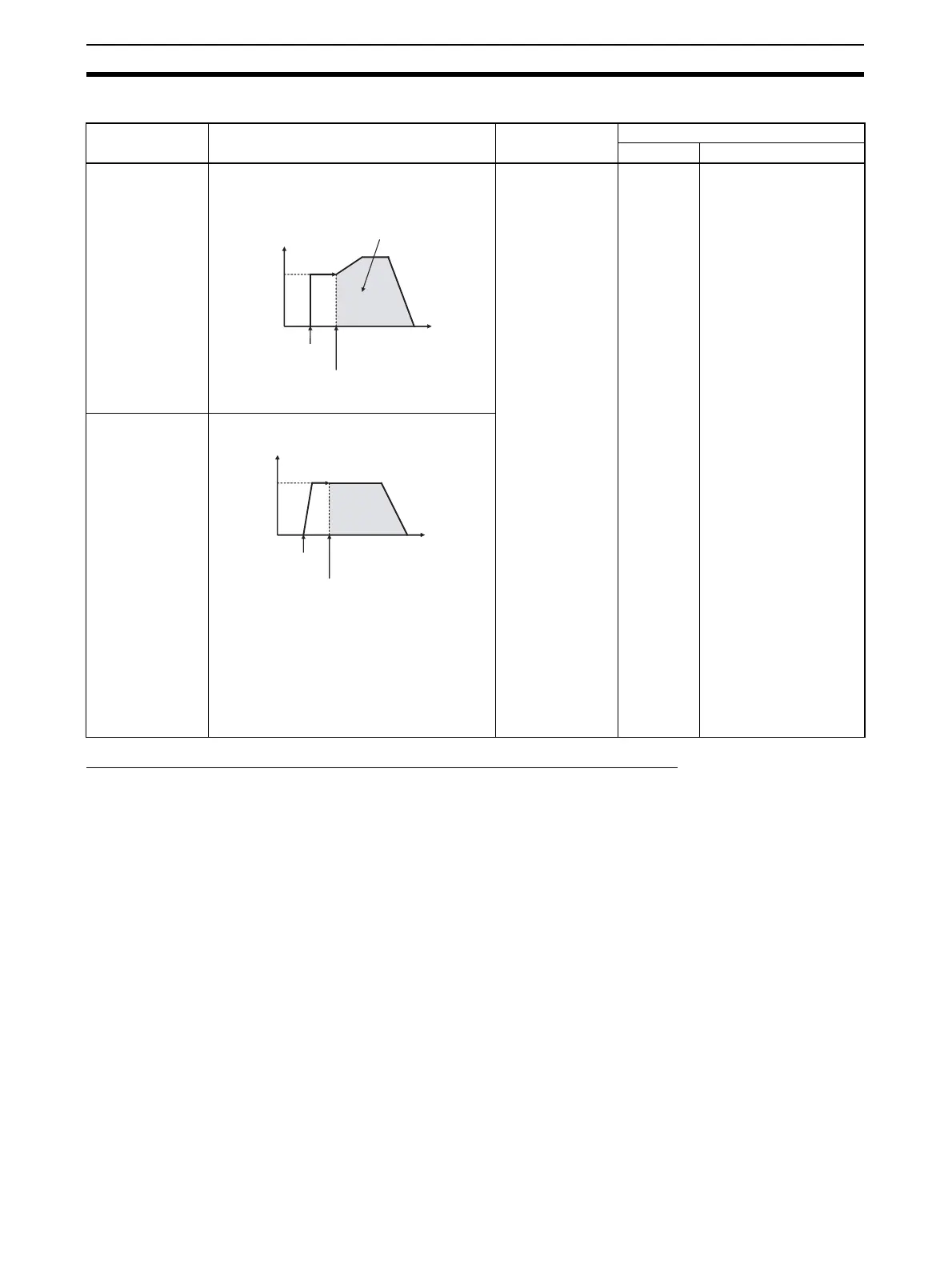
Switching from Continuous Mode (Speed Control) to Independent Mode (Positioning)
Conditions Required to Execute an Instruction During Operation
The following table shows the pulse output instructions that can be executed
while another pulse output instruction is being executed.
When positioning is being performed in independent mode, another indepen-
dent mode instruction can be executed. When speed control is being per-
formed in continuous mode, another continuous mode instruction can be
executed. PLS2(887) is only instruction that can be used to switch between
modes. (PLS2(887) can switch to a positioning operation from a continuous
mode operation started with ACC(888).)
Example applica-
tion
Frequency changes Description Procedure
Instruction Settings
Change from speed
control to fixed dis-
tance positioning
during operation
PLS2(887) can be
executed during a
speed control oper-
ation started with
ACC(888) to
change to position-
ing operation.
Note An error will
occur if a
constant
speed can-
not be
achieved
after switch-
ing the mode.
If this hap-
pens, the
instruction
execution will
be ignored
and the previ-
ous opera-
tion will be
continued.
ACC(888)
(Continu-
ous)
PLS2(887)
•Port
Acceleration rate
Deceleration rate
Target frequency
Number of pulses
Note The starting fre-
quency is ignored.
Fixed distance feed
interrupt
Pulse frequency
Target
frequency
Outputs the number of
pulses specified in
PLS2(887) (Both relative
and absolute pulse
specification can be used.)
Execution of
ACC(888)
(continuous) Execution of
PLS2(887)
Time
Pulse
frequency
Present
frequency
Execution of
ACC(888)
(continuous) Execution of
PLS2(887) with the
following settings
Number of pulses = number
of pulses until stop
Relative pulse specification
Target frequency = present
frequency
Acceleration rate = Not 0
Deceleration rate = target
deceleration rate
Time

Table of Contents

Question and Answer IconNeed help?

Do you have a question about the Omron CJ1M-CPU21 and is the answer not in the manual?

Omron CJ1M-CPU21 Specifications

General IconGeneral
CPU TypeCJ1M
Model NumberCJ1M-CPU21
Data Memory Capacity32K words
Operating Voltage24 VDC
Operating Temperature0 to 55 °C
Execution Speed0.1 μs (basic instructions)
Serial CommunicationRS-232C
Expansion CapabilityUp to 3 expansion units
Programming LanguageLadder logic, structured text
Built-in I/O PointsNo built-in I/O

Summary

PRECAUTIONS

1 Intended Audience

Identifies target personnel for the manual, requiring knowledge of electrical and FA systems.

2 General Precautions

Emphasizes operating products as specified and consulting OMRON for critical applications.

3 Safety Precautions

Crucial warnings about PLC operation, memory modification, and handling electrical components to prevent injury.

4 Operating Environment Precautions

Guidelines on avoiding hazardous locations like direct sunlight, extreme temperatures, or corrosive environments.

5 Application Precautions

Precautions for system setup, grounding, power supply handling, and component mounting during operation.

6 Conformance to EC Directives

Details on compliance with EMC and Low Voltage Directives for safe system integration.

SECTION 1 Features

1-1 Features

Overview of CJ1M CPU Units' high-speed, advanced, micro-sized PLCs with built-in I/O.

1-2 Version Upgrades for CJ1M CPU Units

Details on functional improvements from unit version upgrades for CJ1M CPU Units.

1-3 Functions Listed by Purpose

Categorization of built-in I/O functions based on their specific purpose.

SECTION 2 Overview

2-1 Allocations for Built-in CPU Unit Inputs

Mapping of physical inputs to internal addresses and their functional assignments.

2-2 Allocations for Built-in CPU Unit Outputs

Mapping of physical outputs to internal addresses and their functional assignments.

2-3 Allocations for Origin Search Function

Details on I/O points utilized by the origin search function for pulse outputs.

SECTION 3 I/O Specifications and Wiring

3-1 I/O Specifications

Electrical and functional specifications for built-in inputs and outputs, including voltage and current ratings.

3-2 Wiring

Information on connector pin allocations and wiring methods for system connections.

3-3 Wiring Examples

Practical illustrations of various I/O connection configurations for different devices.

SECTION 4 Data Area Allocation and PLC Setup Settings

4-1 Data Area Allocation for Built-in I/O

Allocation of memory words and bits for built-in I/O usage.

4-2 PLC Setup Settings

Configuration parameters within the PLC for managing built-in I/O functionality.

4-3 Auxiliary Area Data Allocation

Allocation of auxiliary area words and bits related to built-in inputs and outputs.

4-4 Flag Operations during Pulse Output

Explanation of how flags change relative to pulse output operations and timing.

SECTION 5 High-speed Counter/Pulse Output Instructions

5-1 MODE CONTROL: INI(880)

Controls operations for high-speed counters and pulse outputs, including starting/stopping and PV changes.

5-2 HIGH-SPEED COUNTER PV READ: PRV(881)

Reads Present Values (PVs) and status information for high-speed counters and pulse outputs.

5-3 COUNTER FREQUENCY CONVERT: PRV2(883)

Converts pulse frequency to rotational speed or total revolutions.

5-4 REGISTER COMPARISON TABLE: CTBL(882)

Registers comparison tables and performs target or range comparisons for high-speed counter PVs.

5-5 SPEED OUTPUT: SPED(885)

Sets output pulse frequency and starts pulse output without acceleration/deceleration.

5-6 SET PULSES: PULS(886)

Sets the number of output pulses for SPED(885) or ACC(888) in independent mode.

5-7 PULSE OUTPUT: PLS2(887)

Outputs specified pulses with acceleration/deceleration, supporting target changes.

5-8 ACCELERATION CONTROL: ACC(888)

Outputs pulses with specified acceleration/deceleration rates, supporting mode changes.

5-9 ORIGIN SEARCH: ORG(889)

Performs origin search or origin return operations using specified methods and parameters.

5-10 PULSE WITH VARIABLE DUTY FACTOR: PWM(891)

Generates PWM pulse outputs with a specified duty factor and frequency.

SECTION 6 Built-in I/O Function Descriptions

6-1 Built-in Inputs

Detailed description of the types, allocations, and specifications of built-in inputs.

6-2 Built-in Outputs

Detailed description of the types, allocations, and specifications of built-in outputs.

6-3 Origin Search and Origin Return Functions

Detailed explanation of origin search and return operations and their parameters.

SECTION 7 Programming Examples

7-1 Built-in Outputs

Practical examples illustrating the programming of built-in output functions.

Related product manuals