EasyManua.ls Logo

Omron CJ1M-CPU21 User Manual

Omron CJ1M-CPU21
267 pages
To Next Page IconTo Next Page
To Previous Page IconTo Previous Page
Page #140 background imageLoading...
Page #140 background image
111
ACCELERATION CONTROL: ACC(888) Section 5-8
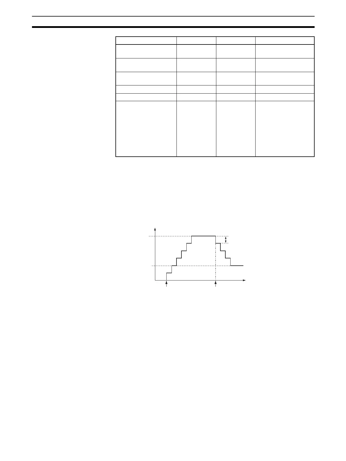
Description ACC(888) starts pulse output on the port specified in P using the mode speci-
fied in M using the target frequency and acceleration/deceleration rate speci-
fied in S. The frequency is increased every pulse control period (4 ms) at the
acceleration rate specified in S until the target frequency specified in S is
reached.
Pulse output is started each time ACC(888) is executed. It is thus normally
sufficient to use the differentiated version (@ACC(888)) of the instruction or
an execution condition that is turned ON only for one scan.
In independent mode, pulse output stops automatically when the specified
number of pulses has been output. In continuous mode, pulse output contin-
ues until it is stopped from the program.
An error will occur if an attempt is made to switch between independent and
continuous mode during pulse output.
With the CJ1M CPU Units, PLS2(887) can be executed during pulse output
for ACC(888) in either independent or continuous mode, and during accelera-
tion, constant speed, or deceleration. (See note.) ACC(888) can also be exe-
cuted during pulse output for PLS2(887) during acceleration, constant speed,
or deceleration.
Note Executing PLS2(887) during speed control with ACC(888) (continuous mode)
with the same target frequency as ACC(888) can be used to achieved inter-
rupt feeding of a fixed distance. Acceleration will not be performed by
PLS2(887) for this application, but if the acceleration rate is set to 0, the Error
Flag will turn ON and PLS2(887) will not be executed. Always set the acceler-
ation rate to a value other than 0.
Indirect DM/EM
addresses in binary
--- --- @ D00000 to @
D32767
Indirect DM/EM
addresses in BCD
--- --- *D00000 to *D32767
Constants See description
of operand.
See description
of operand.
---
Data Registers --- --- ---
Index Registers --- --- ---
Indirect addressing
using Index Registers
--- --- ,IR0 to ,IR15
–2048 to +2047 ,IR0 to
–2048 to +2047 ,IR15
DR0 to DR15, IR0 to
IR15
,IR0+(++) to ,IR15+(++)
,–(– –)IR0 to, –(–
)IR15
Area P M S
Target frequency
Time
Acceleration/deceleration rate
ACC
(
888
)
executed.
Pulse frequency
ACC(888) executed.

Table of Contents

Question and Answer IconNeed help?

Do you have a question about the Omron CJ1M-CPU21 and is the answer not in the manual?

Omron CJ1M-CPU21 Specifications

General IconGeneral
CPU TypeCJ1M
Model NumberCJ1M-CPU21
Data Memory Capacity32K words
Operating Voltage24 VDC
Operating Temperature0 to 55 °C
Execution Speed0.1 μs (basic instructions)
Serial CommunicationRS-232C
Expansion CapabilityUp to 3 expansion units
Programming LanguageLadder logic, structured text
Built-in I/O PointsNo built-in I/O

Summary

PRECAUTIONS

1 Intended Audience

Identifies target personnel for the manual, requiring knowledge of electrical and FA systems.

2 General Precautions

Emphasizes operating products as specified and consulting OMRON for critical applications.

3 Safety Precautions

Crucial warnings about PLC operation, memory modification, and handling electrical components to prevent injury.

4 Operating Environment Precautions

Guidelines on avoiding hazardous locations like direct sunlight, extreme temperatures, or corrosive environments.

5 Application Precautions

Precautions for system setup, grounding, power supply handling, and component mounting during operation.

6 Conformance to EC Directives

Details on compliance with EMC and Low Voltage Directives for safe system integration.

SECTION 1 Features

1-1 Features

Overview of CJ1M CPU Units' high-speed, advanced, micro-sized PLCs with built-in I/O.

1-2 Version Upgrades for CJ1M CPU Units

Details on functional improvements from unit version upgrades for CJ1M CPU Units.

1-3 Functions Listed by Purpose

Categorization of built-in I/O functions based on their specific purpose.

SECTION 2 Overview

2-1 Allocations for Built-in CPU Unit Inputs

Mapping of physical inputs to internal addresses and their functional assignments.

2-2 Allocations for Built-in CPU Unit Outputs

Mapping of physical outputs to internal addresses and their functional assignments.

2-3 Allocations for Origin Search Function

Details on I/O points utilized by the origin search function for pulse outputs.

SECTION 3 I/O Specifications and Wiring

3-1 I/O Specifications

Electrical and functional specifications for built-in inputs and outputs, including voltage and current ratings.

3-2 Wiring

Information on connector pin allocations and wiring methods for system connections.

3-3 Wiring Examples

Practical illustrations of various I/O connection configurations for different devices.

SECTION 4 Data Area Allocation and PLC Setup Settings

4-1 Data Area Allocation for Built-in I/O

Allocation of memory words and bits for built-in I/O usage.

4-2 PLC Setup Settings

Configuration parameters within the PLC for managing built-in I/O functionality.

4-3 Auxiliary Area Data Allocation

Allocation of auxiliary area words and bits related to built-in inputs and outputs.

4-4 Flag Operations during Pulse Output

Explanation of how flags change relative to pulse output operations and timing.

SECTION 5 High-speed Counter/Pulse Output Instructions

5-1 MODE CONTROL: INI(880)

Controls operations for high-speed counters and pulse outputs, including starting/stopping and PV changes.

5-2 HIGH-SPEED COUNTER PV READ: PRV(881)

Reads Present Values (PVs) and status information for high-speed counters and pulse outputs.

5-3 COUNTER FREQUENCY CONVERT: PRV2(883)

Converts pulse frequency to rotational speed or total revolutions.

5-4 REGISTER COMPARISON TABLE: CTBL(882)

Registers comparison tables and performs target or range comparisons for high-speed counter PVs.

5-5 SPEED OUTPUT: SPED(885)

Sets output pulse frequency and starts pulse output without acceleration/deceleration.

5-6 SET PULSES: PULS(886)

Sets the number of output pulses for SPED(885) or ACC(888) in independent mode.

5-7 PULSE OUTPUT: PLS2(887)

Outputs specified pulses with acceleration/deceleration, supporting target changes.

5-8 ACCELERATION CONTROL: ACC(888)

Outputs pulses with specified acceleration/deceleration rates, supporting mode changes.

5-9 ORIGIN SEARCH: ORG(889)

Performs origin search or origin return operations using specified methods and parameters.

5-10 PULSE WITH VARIABLE DUTY FACTOR: PWM(891)

Generates PWM pulse outputs with a specified duty factor and frequency.

SECTION 6 Built-in I/O Function Descriptions

6-1 Built-in Inputs

Detailed description of the types, allocations, and specifications of built-in inputs.

6-2 Built-in Outputs

Detailed description of the types, allocations, and specifications of built-in outputs.

6-3 Origin Search and Origin Return Functions

Detailed explanation of origin search and return operations and their parameters.

SECTION 7 Programming Examples

7-1 Built-in Outputs

Practical examples illustrating the programming of built-in output functions.

Related product manuals