30
Wiring Section 3-2
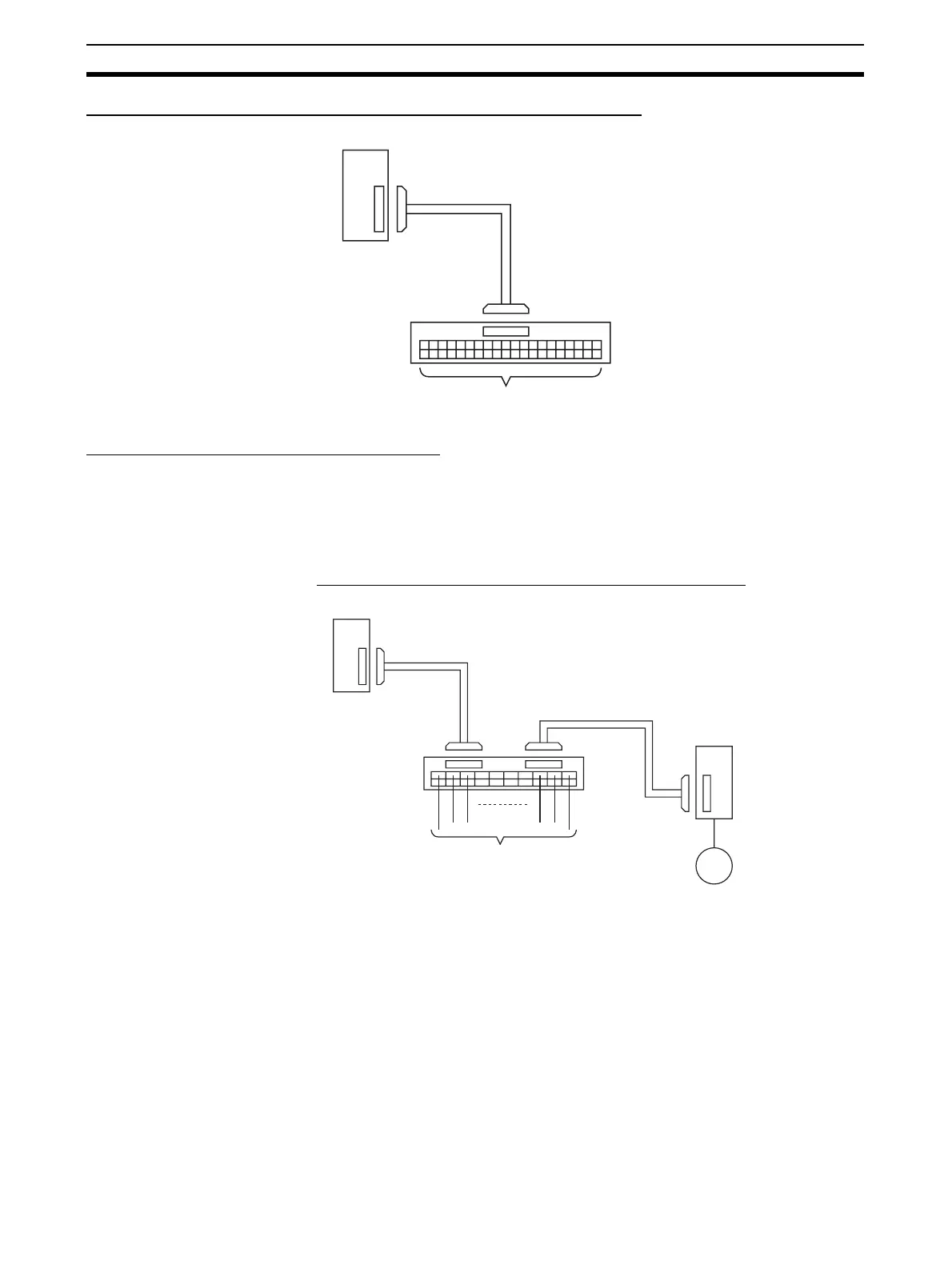
Standard Connection Method (Not for OMRON Servo Drivers)
Connecting to an OMRON Servo Driver
The following cable and Relay Unit can be used when connecting an OMRON
Servo to the CJ1M CPU Unit's built-in I/O. The configurations shown in the fol-
lowing diagrams will make the necessary Servo Driver connections for the
positioning and origin search functions (Origin Input Signal, Origin Proximity
Input Signal, Positioning Completed Signal, and Error Counter Reset Output).
One-axis Servo Driver
Connection (Connecting
Pulse Output 0)
OMRON
SMARTSTEP A-series or UE-series Servo Driver
Note When using a One-axis Relay Unit (connected to pulse output 0), general-pur-
pose outputs 2 and 3 (OUT2 and OUT3) and PWM(891) output 1 (OUT5) can-
not be used.
XW2Z-100K (1 m)
XW2Z-150K (1.5 m)
XW2Z-200K (2 m)
XW2Z-300K (3 m)
XW2Z-500K (5 m)
CJ1M CPU Unit
XW2Z-@@K
Connecting Cable
Terminal Block
XW2D-40G6 (Small)
XW2B-40G5 (Standard)
XW2B-40G4 (Standard)
Connector-Terminal
Unit Conversion
CJ1M CPU Unit
XW2Z-100J-A26
Connecting Cable (1 m)
XW2B-20J6-8A
Relay Unit
(for 1 axis)
Terminal Block (20P, see note)
• 4 General-purpose inputs (IN6 to IN9)
• 1 input such as the Near Origin Input
SMARTSTEP A-series
Connecting Cable
XW2Z-100J-B5 (1 m)
XW2Z-200J-B5 (2 m)
A-series or
UE-series
Servomotor
SMARTSTEP
A-series or
UE-series
Servomotor

 Loading...


