28
Wiring Section 3-2
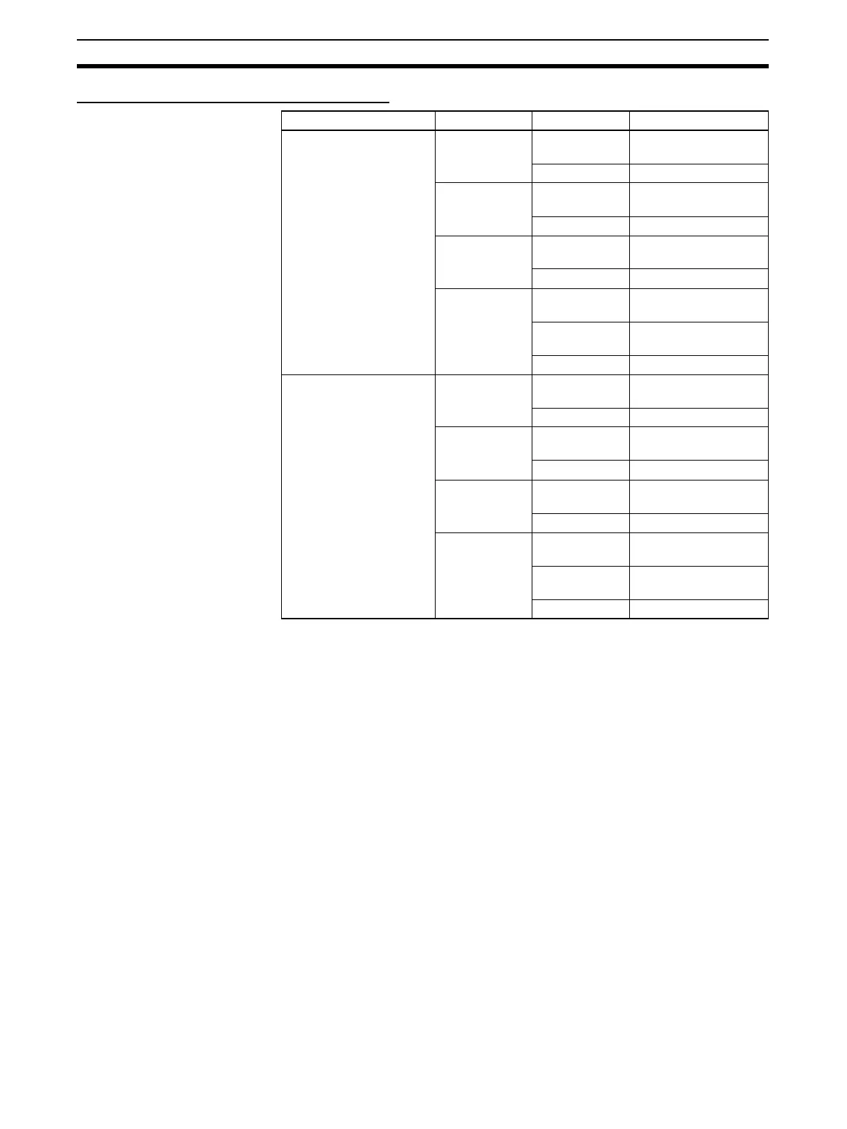
I/O Used in the Origin Search Function
3-2-3 Wiring Methods
To connect to a Terminal Block, use an OMRON Cable preassembled with the
special connector or attach the special connector (sold separately) to a cable
yourself.
Note 1. Do not supply a voltage to the input terminals that exceeds the I/O circuit's
specified input voltage range. Likewise, do not connect a voltage or load
that exceeds the output circuit's max. switching capacity.
2. When the power supply terminals are marked with + and
− indicators, verify
that the power supply wires have not been reversed accidentally.
3. When the equipment is subject to EC Directives (the Low Voltage Direc-
tives), a DC power supply with reinforced insulation or double insulation
must be used for the I/O power supply.
4. Double-check all connector wiring before turning ON the power supply.
5. Do not pull on the cable. Doing so may separate the cable from the con-
nector.
6. Do not bend the cable too sharply. Doing so may damage the cable.
7. The connector pin allocation of the CJ1W-ID232/262 and OD233/263 con-
nectors is not compatible. The Unit's internal circuits may be damaged if
one of these connectors is connected.
8. Do not connect a 24-V DC output device to a line driver input. Doing so
may damage the internal circuits.
Output number Code Pin No. Content
Origin search 0 IN0 1 Origin Input Signal,
24 V DC
50 V
IN1 2 Origin Proximity Input
Signal, 24 V DC
60 V
IN4 13 Positioning Completed
Signal, 24 V DC
17 0 V
OUT4 35 Error Counter Reset
Output
37 Power supply input
(+V) for the output
39 or 40 Output COM
Origin search 1 IN2 7 Origin Input Signal,
24 V DC
11 0 V
IN3 8 Origin Proximity Input
Signal, 24 V DC
12 0 V
IN5 14 Positioning Completed
Signal, 24 V DC
18 0 V
OUT5 36 Error Counter Reset
Output
37 Power supply input
(+V) for the output
39 or 40 Output COM

 Loading...


