41
Wiring Examples Section 3-3
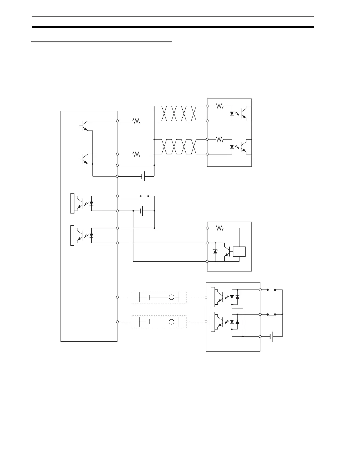
Connection Example for Operating Mode 0
In operating mode 0, the origin location is determined when the rising edge of
the Origin Input Signal is detected (up-differentiation.) The Error Counter
Reset Output and Positioning Completed Signal are not used.
In this example, a stepping motor driver is used and a sensor is connected to
the Origin Input Signal terminal.
1.6 kΩ
31
32
37
39, 40
1.6 kΩ
24 V DC
+CW
−CW
+CW
−CW
2 (24 V DC)
6 (0 V)
1
(24 V DC)
5 (0 V)
+V
0 V
24 V DC
A54009
000001 A54009
000001
A54008
000000 A54008
000000
IN 1
IN 0
COM
B0
A0
24 V DC
+
A8,
B8
Operation Mode 0
Stepping motor driver
(5-V input)
CW output
(pulse output 0)
CCW
output
(pulse
output 0)
Output
power
supply
input
Origin Proximity
Input Signal
(origin search 0)
Origin Input
Signal (origin
search 0)
N.O. contact
E2R-A01 Proximity
Sensor (NPN output)
Output COM
CCW Limit
Input Signal
CW Limit
Input Signal
Signal
Switch
circuit
CJ1W-ID211 Input Unit
N.C.
contact
N.C.
contact

 Loading...


