23
Wiring Section 3-2
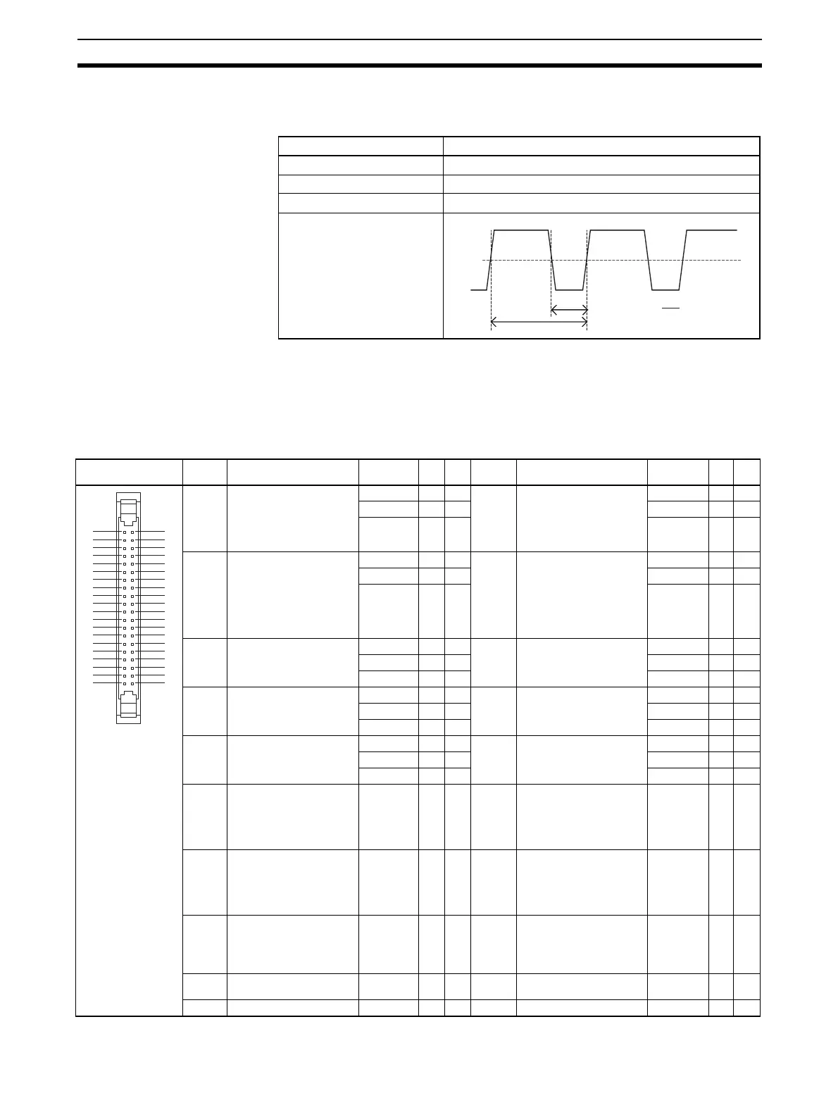
PWM(891) Output
Specifications (OUT4 and
OUT5)
Note The CJ1W-CPU21 supports only OUT4. OUT5 cannot be used.
3-2 Wiring
3-2-1 Connector Pin Allocations
Item Specifications
Max. switching capacity 300 mA, 4.75 to 26.4 V DC
Max. output frequency 1 kHz
PWM(891) output accuracy ON duty: +5%/−0% for a 1-kHz pulse output
Output waveform
Pin layout
Code Name Input
signal type
Pin
No.
*1 Code Name Input
signal type
Pin
No.
*1
IN0 • General-purpose input 0
• Interrupt input 0
• Quick-response input 0
• Origin search 0
(Origin Input Signal)
24 V DC 1 A1 IN1 • General-purpose input 0
• Interrupt input 0
• Quick-response input 0
• Origin search 0
(Origin Proximity Input
Signal)
24 V DC 2 B1
LD+ 3 A2 LD+ 4 B2
0 V/LD
− 5A3 0 V/LD− 6B3
IN2 • General-purpose input 2
• Interrupt input 2
• Quick-response input 2
• High-speed counter 1
(Phase-Z/Reset input)
• Origin search 1
(Origin Input Signal)
24 V DC 7 A4 IN3 • General-purpose input 3
• Interrupt input 3
• Quick-response input 3
• High-speed counter 0
(Phase-Z/Reset input)
• Origin search 1
(Origin Proximity Input
Signal)
24 V DC 8 B4
LD+ 9 A5 LD+ 10 B5
0 V/LD
− 11 A6 0 V/LD− 12 B6
IN4 • General-purpose input 4
• Origin search 0
(Positioning Completed
Signal)
24 V DC 13 A7 IN5 • General-purpose input 5
• Origin search 1
(Positioning Completed
Signal)
24 V DC 14 B7
LD+ 15 A8 LD+ 16 B8
0 V/LD
− 17 A9 0 V/LD− 18 B9
IN6 • General-purpose input 6
• High-speed counter 1
(Phase-A, Increment, or
Count input)
24 V DC 19 A10 IN7 • General-purpose input 7
• High-speed counter 1
(Phase-B, Decrement, or
Direction input)
24 V DC 20 B10
LD+ 21 A11 LD+ 22 B11
0 V/LD
− 23 A12 0 V/LD− 24 B12
IN8 • General-purpose input 8
• High-speed counter 0
(Phase-A, Increment, or
Count input)
24 V DC 25 A13 IN9 • General-purpose input 9
• High-speed counter 0
(Phase-B, Decrement, or
Direction input)
24 V DC 26 B13
LD+ 27 A14 LD+ 28 B14
0 V/LD
− 29 A15 0 V/LD− 30 B15
OUT0 General-purpose output 0
• In CW/CCW mode:
Pulse output 0 (CW)
• In Pulse + Direction
mode:
Pulse output 0 (pulse)
--- 31 A16 OUT1 General-purpose output 1
• In CW/CCW mode:
Pulse output 0 (CCW)
• In Pulse + Direction
mode:
Pulse output 1 (pulse)
--- 32 B16
OUT2 General-purpose output 2
• In CW/CCW mode:
Pulse output 1 (CW)
• In Pulse + Direction
mode:
Pulse output 0 (direction)
--- 33 A17 OUT3 General-purpose output 3
• In CW/CCW mode:
Pulse output 1 (CCW)
• In Pulse + Direction
mode:
Pulse output 1 (direction)
--- 34 B17
OUT4 • General-purpose output 4
• Origin search 0
(Error Counter Reset Out-
put)
• PWM(891) output 0
--- 35 A18 OUT5 • General-purpose output 5
• Origin search 1
(Error Counter Reset Out-
put)
• PWM(891) output 1
*2
--- 36 B18
--- Power supply input (+V) for
the output
--- 37 A19 --- Not used --- 38 B19
--- Output COM --- 39 A20 --- Output COM --- 40 B20
ON
OFF
T
t
ON
50
%
ON duty =
t
ON
T
X 100%
1
3
5
7
9
11
13
15
17
19
21
23
25
27
29
31
33
35
37
39
2
4
6
8
10
12
14
16
18
20
22
24
26
28
30
32
34
36
38
40

 Loading...


