EasyManua.ls Logo

Omron CJ1M-CPU21 User Manual

Omron CJ1M-CPU21
267 pages
To Next Page IconTo Next Page
To Previous Page IconTo Previous Page
Page #156 background imageLoading...
Page #156 background image
127
Built-in Inputs Section 6-1
Restrictions on Interrupt
Inputs (Direct Mode)
Interrupt inputs 0 to 3 cannot be used when built-in inputs IN0 to IN3 are
being used as general-purpose inputs or quick-response inputs.
Interrupt input 3 cannot be used when high-speed counter input 0 is being
used and the high-speed counter 0 reset method is set to Phase-Z signal
+ Software reset.
Interrupt input 2 cannot be used when high-speed counter input 1 is being
used and the high-speed counter 1 reset method is set to Phase-Z signal
+ Software reset.
Interrupt inputs 0 and 1 cannot be used when the origin search function is
enabled for pulse output 0 (enabled in the PLC Setup).
Interrupt inputs 2 and 3 cannot be used when the origin search function is
enabled for pulse output 1 (enabled in the PLC Setup).
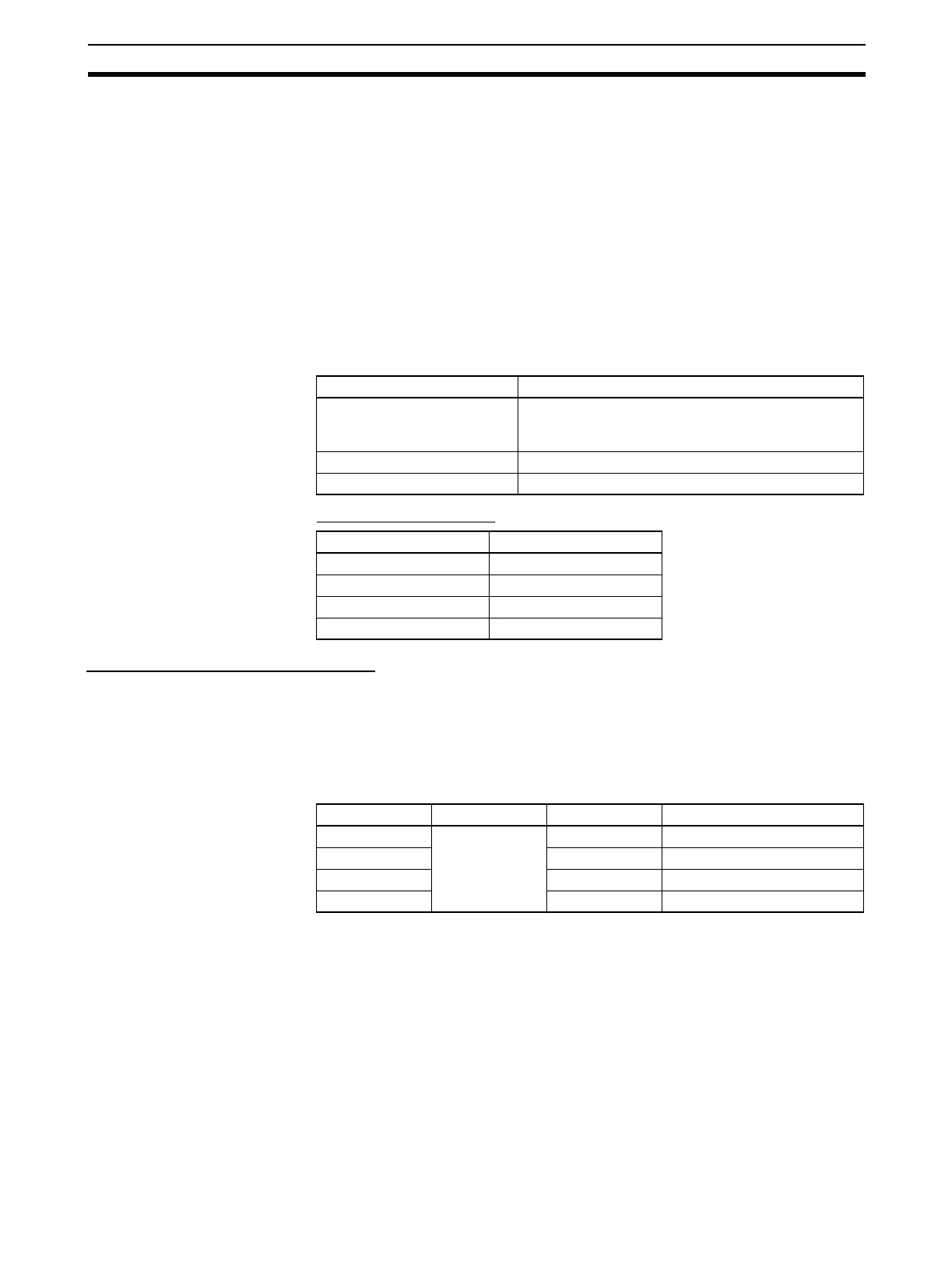
Specifications
Interrupt Task Numbers
Interrupt Inputs (Counter Mode)
Overview This function counts input signals (up or down differentiated) and starts an
interrupt task when the counter PV reaches the SV (or 0 when decrementing.)
The four interrupt inputs control interrupt tasks 140 to 143. The interrupt task
numbers cannot be changed.
Bit Allocations
Item Specifications
Number of inputs 4 inputs (The 4 input terminals are shared with the
quick-response inputs, high-speed counter (Phase-Z
signal), and general-purpose inputs.)
Allocated data area CIO 2960 bits 00 to 03
Interrupt detection Up differentiation or down differentiation
Input bit Interrupt task number
CIO 2960 bit 00 140
CIO 2960 bit 01 141
CIO 2960 bit 02 142
CIO 2960 bit 03 143
Code Word address Bit Function
IN0 CIO 2960 00 Interrupt input 0
IN1 01 Interrupt input 1
IN2 02 Interrupt input 2
IN3 03 Interrupt input 3

Table of Contents

Question and Answer IconNeed help?

Do you have a question about the Omron CJ1M-CPU21 and is the answer not in the manual?

Omron CJ1M-CPU21 Specifications

General IconGeneral
CPU TypeCJ1M
Model NumberCJ1M-CPU21
Data Memory Capacity32K words
Operating Voltage24 VDC
Operating Temperature0 to 55 °C
Execution Speed0.1 μs (basic instructions)
Serial CommunicationRS-232C
Expansion CapabilityUp to 3 expansion units
Programming LanguageLadder logic, structured text
Built-in I/O PointsNo built-in I/O

Summary

PRECAUTIONS

1 Intended Audience

Identifies target personnel for the manual, requiring knowledge of electrical and FA systems.

2 General Precautions

Emphasizes operating products as specified and consulting OMRON for critical applications.

3 Safety Precautions

Crucial warnings about PLC operation, memory modification, and handling electrical components to prevent injury.

4 Operating Environment Precautions

Guidelines on avoiding hazardous locations like direct sunlight, extreme temperatures, or corrosive environments.

5 Application Precautions

Precautions for system setup, grounding, power supply handling, and component mounting during operation.

6 Conformance to EC Directives

Details on compliance with EMC and Low Voltage Directives for safe system integration.

SECTION 1 Features

1-1 Features

Overview of CJ1M CPU Units' high-speed, advanced, micro-sized PLCs with built-in I/O.

1-2 Version Upgrades for CJ1M CPU Units

Details on functional improvements from unit version upgrades for CJ1M CPU Units.

1-3 Functions Listed by Purpose

Categorization of built-in I/O functions based on their specific purpose.

SECTION 2 Overview

2-1 Allocations for Built-in CPU Unit Inputs

Mapping of physical inputs to internal addresses and their functional assignments.

2-2 Allocations for Built-in CPU Unit Outputs

Mapping of physical outputs to internal addresses and their functional assignments.

2-3 Allocations for Origin Search Function

Details on I/O points utilized by the origin search function for pulse outputs.

SECTION 3 I/O Specifications and Wiring

3-1 I/O Specifications

Electrical and functional specifications for built-in inputs and outputs, including voltage and current ratings.

3-2 Wiring

Information on connector pin allocations and wiring methods for system connections.

3-3 Wiring Examples

Practical illustrations of various I/O connection configurations for different devices.

SECTION 4 Data Area Allocation and PLC Setup Settings

4-1 Data Area Allocation for Built-in I/O

Allocation of memory words and bits for built-in I/O usage.

4-2 PLC Setup Settings

Configuration parameters within the PLC for managing built-in I/O functionality.

4-3 Auxiliary Area Data Allocation

Allocation of auxiliary area words and bits related to built-in inputs and outputs.

4-4 Flag Operations during Pulse Output

Explanation of how flags change relative to pulse output operations and timing.

SECTION 5 High-speed Counter/Pulse Output Instructions

5-1 MODE CONTROL: INI(880)

Controls operations for high-speed counters and pulse outputs, including starting/stopping and PV changes.

5-2 HIGH-SPEED COUNTER PV READ: PRV(881)

Reads Present Values (PVs) and status information for high-speed counters and pulse outputs.

5-3 COUNTER FREQUENCY CONVERT: PRV2(883)

Converts pulse frequency to rotational speed or total revolutions.

5-4 REGISTER COMPARISON TABLE: CTBL(882)

Registers comparison tables and performs target or range comparisons for high-speed counter PVs.

5-5 SPEED OUTPUT: SPED(885)

Sets output pulse frequency and starts pulse output without acceleration/deceleration.

5-6 SET PULSES: PULS(886)

Sets the number of output pulses for SPED(885) or ACC(888) in independent mode.

5-7 PULSE OUTPUT: PLS2(887)

Outputs specified pulses with acceleration/deceleration, supporting target changes.

5-8 ACCELERATION CONTROL: ACC(888)

Outputs pulses with specified acceleration/deceleration rates, supporting mode changes.

5-9 ORIGIN SEARCH: ORG(889)

Performs origin search or origin return operations using specified methods and parameters.

5-10 PULSE WITH VARIABLE DUTY FACTOR: PWM(891)

Generates PWM pulse outputs with a specified duty factor and frequency.

SECTION 6 Built-in I/O Function Descriptions

6-1 Built-in Inputs

Detailed description of the types, allocations, and specifications of built-in inputs.

6-2 Built-in Outputs

Detailed description of the types, allocations, and specifications of built-in outputs.

6-3 Origin Search and Origin Return Functions

Detailed explanation of origin search and return operations and their parameters.

SECTION 7 Programming Examples

7-1 Built-in Outputs

Practical examples illustrating the programming of built-in output functions.

Related product manuals