33
Wiring Examples Section 3-3
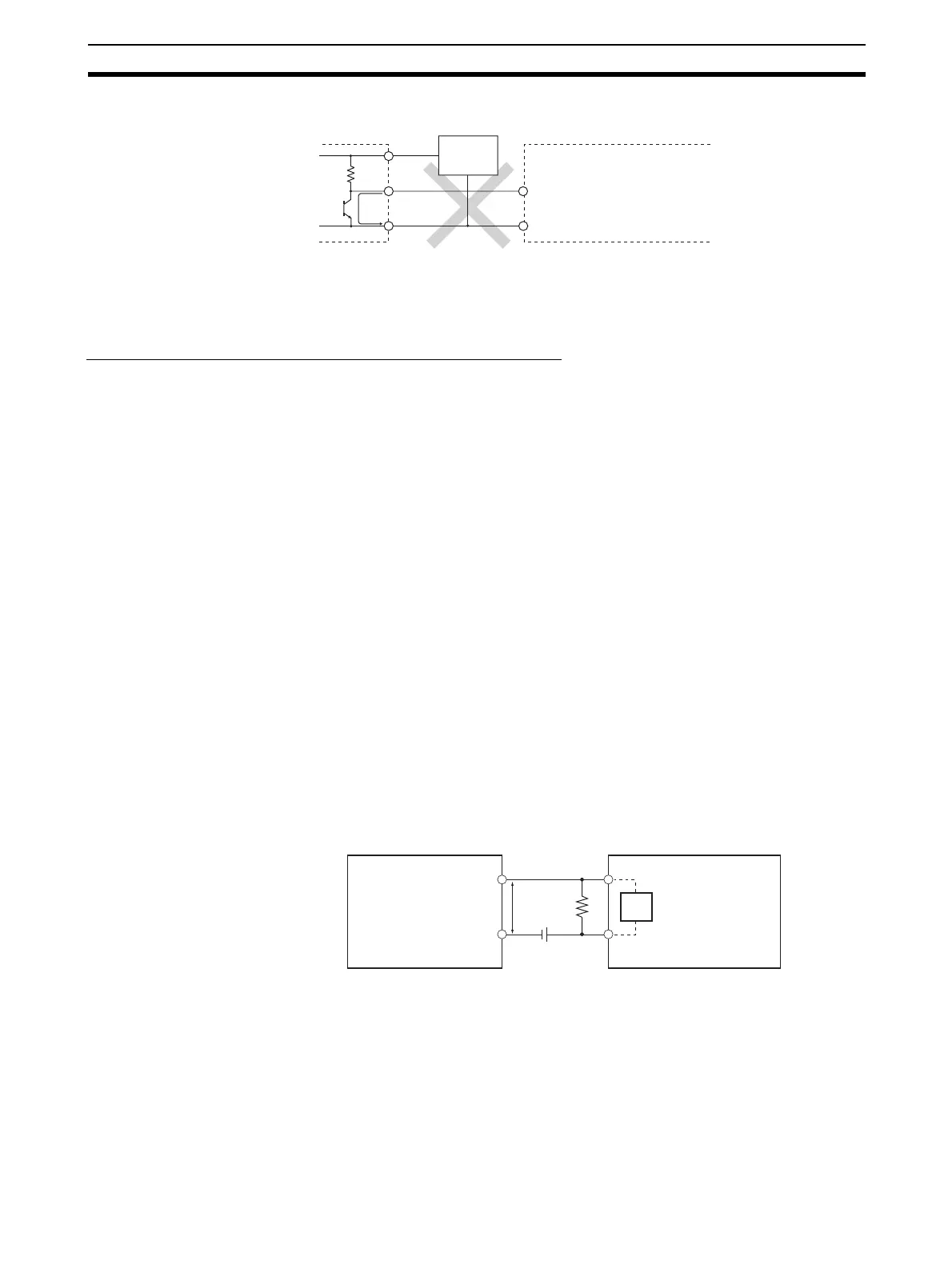
Note Do not use the following wiring with voltage-output devices.
Note The CJ1M CPU Unit's inputs have a set polarity, so the inputs will not go ON if
the wiring is reversed. Always double-check the wiring before turning ON the
power.
Precautions when Connecting Two-wire DC Sensors
Check that the following conditions are met when using a two-wire sensor as
a 24-V DC input device. The sensor may malfunction if the conditions are not
met.
1,2,3... 1. Check the relationship between the PLC's ON voltage and the sensor's re-
sidual voltage.
V
ON
≤ V
CC
− V
R
2. Check the relationship between the PLC's ON current and the sensor's
control output (load current.)
I
OUT
(min.) ≤ I
ON
≤ I
OUT
(max.)
I
ON
= (V
CC
− V
R
− 1.5 [PLC's internal residual voltage]*)/R
IN
Connect a bleeder resistor (R) if I
ON
is less than I
OUT
(min). Use the follow-
ing equation to determine the proper bleeder resistance.
R
≤ (V
CC
− V
R
)/(I
OUT
(min.) − I
ON
)
Power W
≥ (V
CC
− V
R
)
2
/R × 4 [Tolerance]
3. Check the relationship between the PLC's OFF current and the sensor's
leakage current.
I
OFF
≥ I
leak
Connect a bleeder resistor (R) if I
leak
is greater than I
OFF
. Use the following
equation to determine the proper bleeder resistance.
R
≤ R
IN
× V
OFF
/(I
leak
× R
IN
− V
OFF
)
Power W
≥ (V
CC
− V
R
)
2
/R × 4 [Tolerance]
V
CC
: Power supply voltage V
R
: Sensor's residual output voltage
V
ON
: PLC's ON voltage I
OUT
: Sensor's control output (load current)
V
OFF
: PLC's OFF voltage
I
ON
: PLC's ON current I
leak
: Sensor's leakage current
I
OFF
: PLC's OFF current R: Bleeder resistance
R
IN
: PLC's input impedance
4. Precautions Regarding the Sensor Inrush Current
If the sensor power supply is turned ON when the PLC is already ON and
capable of receiving inputs, the sensor's inrush current may cause a false
+
0 V
IN (24 V DC)
IN (0 V)
Output
Sensor
power
supply
CJ1M CPU Unit's
built-in I/O
V
R
R
V
CC
R
IN
Two-wire sensor
CJ1M CPU Unit's
built-in I/O

 Loading...


