126
Built-in Inputs Section 6-1
Specifications
6-1-3 Interrupt Inputs
Interrupt Inputs (Direct Mode)
Overview This function starts an interrupt task when the corresponding input signal (up
or down differentiated) is received. The four interrupt inputs control interrupt
tasks 140 to 143. (The interrupt task numbers cannot be changed.)
Bit Allocations
Procedure
Note Use the MSKS(690) instruction to select the interrupt mode (direct mode or
counter mode.)
Item Specifications
Number of inputs 10 inputs
Allocated data area CIO 2960 bits 00 to 09
Input time constant
(ON response time)
Default: 8 ms
The following settings can be made in the PLC
Setup: 0 ms (no filter), 0.5 ms, 1 ms, 2 ms, 4 ms,
8 ms, 16 ms, or 32 ms.
Code Word address Bit Function
IN0 CIO 2960 00 Interrupt input 0
IN1 01 Interrupt input 1
IN2 02 Interrupt input 2
IN3 03 Interrupt input 3
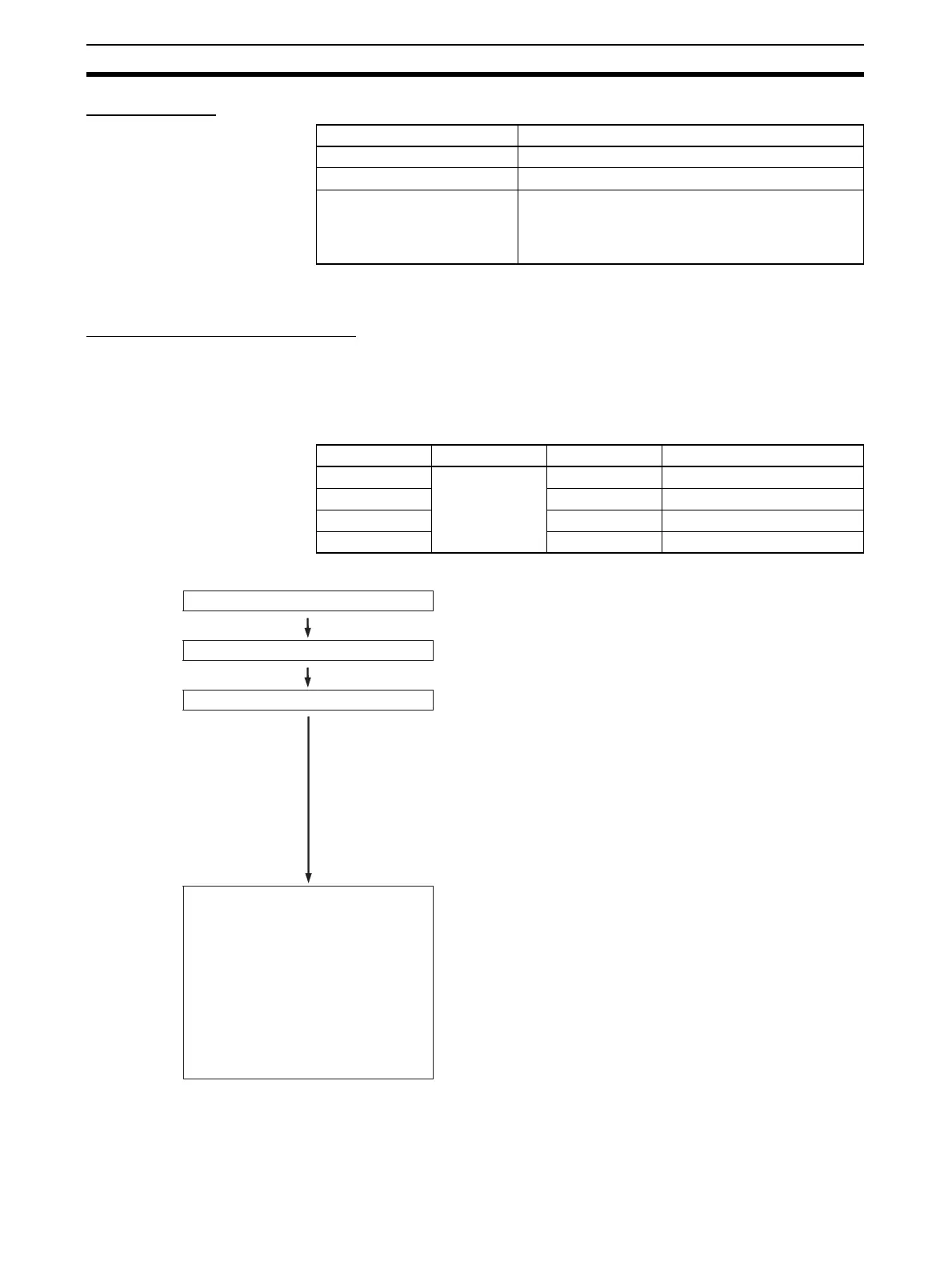
Select interrupt inputs.
Wire inputs.
PLC Setup settings
Ladder program
• IN0 to IN3 (CIO 2960 bits 00 to 03)
• Connect to the selected terminals between
IN0 and IN3.
• When IN0 to IN3 are used as interrupt inputs in direct
mode, make the necessary "input operation settings"
for IN0 to IN3 in Programming Console address 60.
IN0: Set the rightmost digit (bits 00 to 03) to 1 hex.
IN1: Set the second digit (bits 04 to 07) to 1 hex.
IN2: Set the third digit (bits 08 to 11) to 1 hex.
IN3: Set the leftmost digit (bits 12 to 15) to 1 hex.
• Program the corresponding interrupt tasks. Interrupt
tasks 140 to 143 correspond to inputs IN0 to IN3).
• Use the MSKS(690) instruction to specify up or down
differentiation.
Use control data (N) settings 10 to 13 to set up/down
differentiation for inputs IN0 to IN3. Set S=0 to specify
up differentiation or S=1 to specify down
differentiation.
• Use the MSKS(690) instruction to enable the interrupt
inputs in direct mode.
Use control data (N) settings 6 to 9 to specify interrupt
inputs IN0 to IN3. Set S=0 to enable the interrupts in
direct mode.