129
Built-in Inputs Section 6-1
Specifications
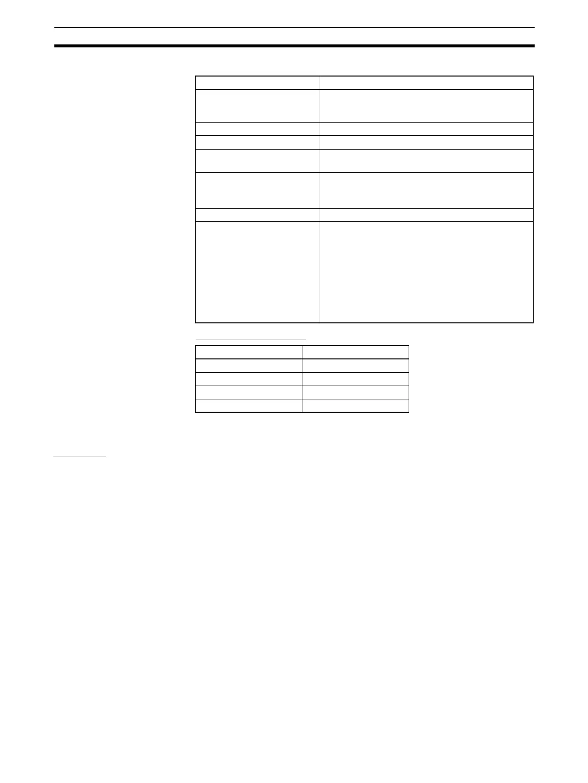
Interrupt Task Numbers
6-1-4 High-speed Counter Inputs
Overview
This function counts pulse signals input at the built-in input terminals.
Any one of the following input signals can be selected as the counter input
mode.
• Differential phase inputs (4x)
• Pulse + direction inputs
• Up/Down pulse inputs
• Increment pulse inputs
The present counts are contained in the High-speed Counter PVs (A270 to
A273.)
• The counting mode can be set to linear mode or ring mode counting.
• The counter reset method can be set to Phase-Z signal + Software reset
or Software reset.
• An interrupt task can be started when the high-speed counter PV meets
the preset comparison condition. Either one of these comparison meth-
ods can be used:
• Target value comparison
• Range comparison
• Counting can be stopped temporarily with the counters Gate Bit (Gate
function.)
Item Specifications
Number of inputs 4 inputs (The 4 input terminals are shared with the
quick-response inputs, high-speed counter (Phase-Z
signal), and general-purpose inputs.)
Allocated data area CIO 2960 bits 00 to 03
Count pulse detection Up differentiation or down differentiation
Count method Incrementing or decrementing (Set with the
MSKS(690) instruction.)
Count range 0001 to FFFF hex (16 bits)
(The SVs are set in Auxiliary Area words A532 to
A535.)
Response frequency Single phase: 1 kHz x 4 inputs
Storage priority for the inter-
rupt input (counter mode) PVs
A536 to A539
•PVs can be read with the PRV(881) instruction.
•PVs can be changed with the INI(880) instruction.
Note
•PVs are retained when the power is turned ON.
•PVs are cleared when operation starts.
•PVs are refreshed when a interrupt occurs.
•PVs are refreshed when the INI(880) instruction is
executed to change the PV.
Input bit Interrupt task number
CIO 2960 bit 00 140
CIO 2960 bit 01 141
CIO 2960 bit 02 142
CIO 2960 bit 03 143