24
Wiring Section 3-2
*1: These are the pins on the XW2D-@@G@ Terminal Block.
*2: PWM(891) output 1 can be used only with the CJ1M-CPU22/CPU23.
3-2-2 Connector Pins Used by Each Function
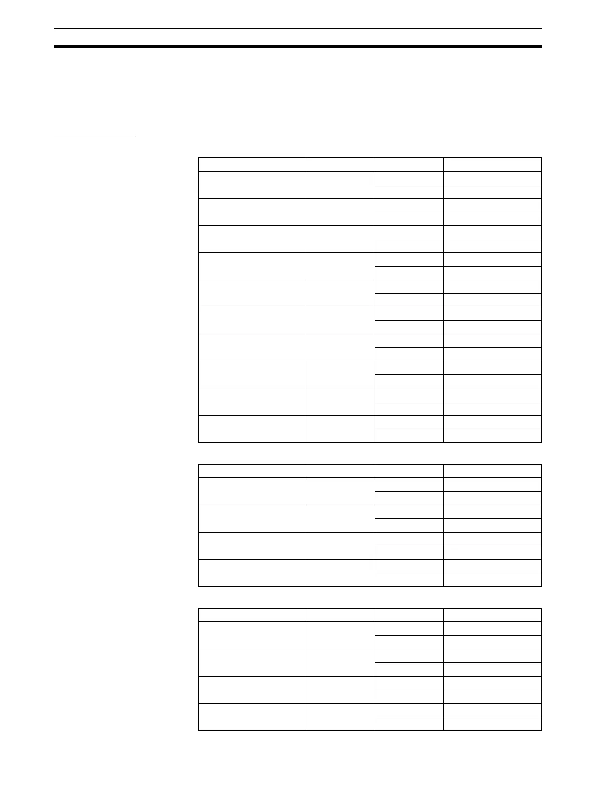
Built-in Inputs
General-purpose Inputs
Interrupt Inputs
Quick-response Inputs
Input number Code Pin No. Content
General-purpose input 0 IN0 1 24 V DC
50 V
General-purpose input 1 IN1 2 24 V DC
60 V
General-purpose input 2 IN2 7 24 V DC
11 0 V
General-purpose input 3 IN3 8 24 V DC
12 0 V
General-purpose input 4 IN4 13 24 V DC
17 0 V
General-purpose input 5 IN5 14 24 V DC
18 0 V
General-purpose input 6 IN6 19 24 V DC
23 0 V
General-purpose input 7 IN7 20 24 V DC
24 0 V
General-purpose input 8 IN8 25 24 V DC
29 0 V
General-purpose input 9 IN9 26 24 V DC
30 0 V
Input number Code Pin No. Content
Interrupt input 0 IN0 1 24 V DC
50 V
Interrupt input 1 IN1 2 24 V DC
60 V
Interrupt input 2 IN2 7 24 V DC
11 0 V
Interrupt input 3 IN3 8 24 V DC
12 0 V
Input number Code Pin No. Content
Quick-response input 0 IN0 1 24 V DC
50 V
Quick-response input 1 IN1 2 24 V DC
60 V
Quick-response input 2 IN2 7 24 V DC
11 0 V
Quick-response input 3 IN3 8 24 V DC
12 0 V

 Loading...


