40
Wiring Examples Section 3-3
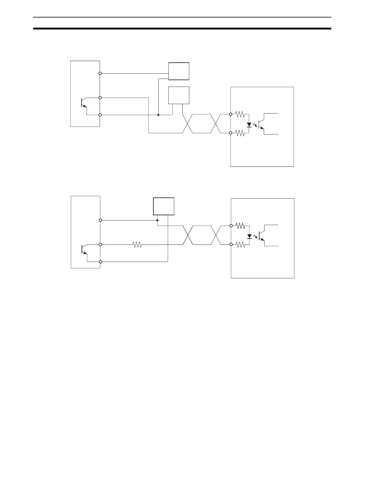
3-3-5 Error Counter Reset Output Connection Examples
3-3-6 Motor Driver Connection Examples
This section provides examples of connections to pulse output 0. Refer to 3-2
Wiring for details when using pulse output 1.
Note 1. Any NC input terminals for unused inputs should be connected to the pow-
er supply and turned ON.
2. Use shielded cable for connections to stepping motor drivers and servo
drivers. Attach the shield to the FG terminals at both the NC Unit end and
driver end of the cable.
3. When using an open-collector connection, the cable to the motor driver
must not exceed 3 m. When using a line driver connection, the cable to the
motor driver must not exceed 5 m.
DC24V
37/38
35/36
39, 40
+
−
−
+
+ECRST
−ECRST
15
14
37/38
35/36
39, 40
1.6 kΩ
+
−
+ECRST
−ECRST
15
14
CJ1M CPU Unit
Output
power
supply
input
24-V DC
power
supply
5-V DC
power
supply
OMRON R88D-WT Servo
Driver
CJ1M CPU Unit
Output
power
supply
input
24-V DC
power
supply
OMRON R88D-WT Servo
Driver

 Loading...


