EasyManua.ls Logo

Omron CJ1M-CPU21 User Manual

Omron CJ1M-CPU21
267 pages
To Next Page IconTo Next Page
To Previous Page IconTo Previous Page
Page #256 background imageLoading...
Page #256 background image
227
Appendix C
Interrupt Response Times
Note The actual performance depends on a variety of factors that affect CPU Unit operation such as the func-
tion's operating conditions, user program complexity, and cycle time. Use the performance specifica-
tions as guidelines, not absolute values.
Built-in Interrupt Input Response Time
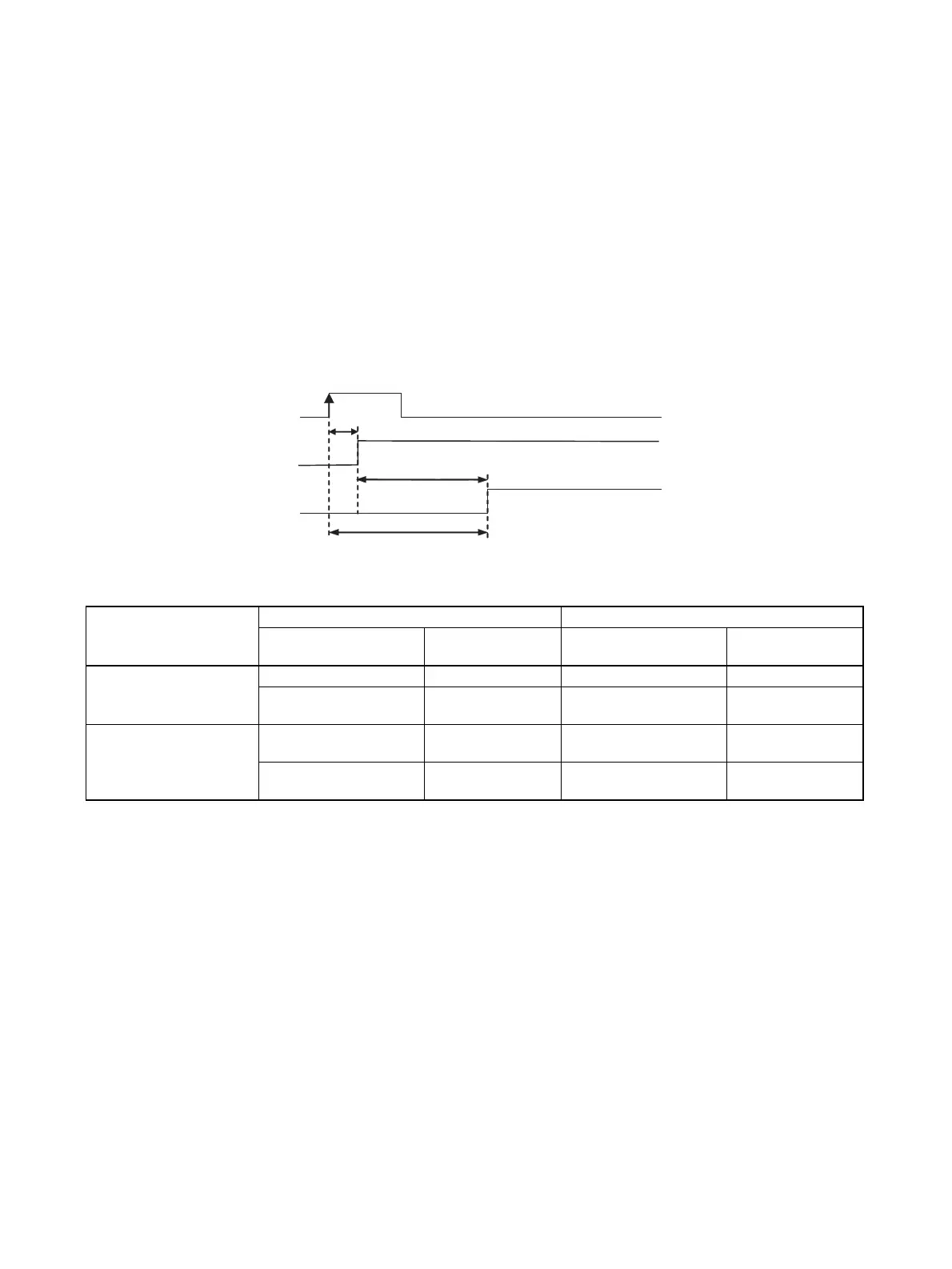
The interrupt response time is the time it takes between an OFF-to-ON signal (or ON-to-OFF signal for down-
differentiation) at the built-in interrupt input terminal until the corresponding I/O interrupt task is actually exe-
cuted. The total response time is the sum of the hardware response time and software response time.
Note The term a is the delay caused when there is a conflict with another interrupt process. In general, this
delay may be anywhere between 6 µs and 150 µs long.
Item CJ1M-CPU22/23 CJ1M-CPU21
Interrupt response
time
Counter interrupts Interrupt response
time
Counter interrupts
Hardware interrupt
response time
Up-differentiation 30 µs --- Up-differentiation 30 µs ---
Down-differentiation
150 µs
--- Down-differentiation
150 µs
---
Software interrupt
response time
Minimum: 93 µs Maximum: 203 µs +
α
Minimum: 159 µs 187 µs
Maximum: 209 µs + α
(See note.)
Minimum: 103 µs Maximum: 289 µs + α
(See note.)
287 µs
Input
Signal read at the
built-in input terminal
Interrupt task execution
Hardware response time
Software response time
Built-in interrupt input
response time
Built-in interrupt input response time = Hardware interrupt response time + Software interrupt response time

Table of Contents

Question and Answer IconNeed help?

Do you have a question about the Omron CJ1M-CPU21 and is the answer not in the manual?

Omron CJ1M-CPU21 Specifications

General IconGeneral
CPU TypeCJ1M
Model NumberCJ1M-CPU21
Data Memory Capacity32K words
Operating Voltage24 VDC
Operating Temperature0 to 55 °C
Execution Speed0.1 μs (basic instructions)
Serial CommunicationRS-232C
Expansion CapabilityUp to 3 expansion units
Programming LanguageLadder logic, structured text
Built-in I/O PointsNo built-in I/O

Summary

PRECAUTIONS

1 Intended Audience

Identifies target personnel for the manual, requiring knowledge of electrical and FA systems.

2 General Precautions

Emphasizes operating products as specified and consulting OMRON for critical applications.

3 Safety Precautions

Crucial warnings about PLC operation, memory modification, and handling electrical components to prevent injury.

4 Operating Environment Precautions

Guidelines on avoiding hazardous locations like direct sunlight, extreme temperatures, or corrosive environments.

5 Application Precautions

Precautions for system setup, grounding, power supply handling, and component mounting during operation.

6 Conformance to EC Directives

Details on compliance with EMC and Low Voltage Directives for safe system integration.

SECTION 1 Features

1-1 Features

Overview of CJ1M CPU Units' high-speed, advanced, micro-sized PLCs with built-in I/O.

1-2 Version Upgrades for CJ1M CPU Units

Details on functional improvements from unit version upgrades for CJ1M CPU Units.

1-3 Functions Listed by Purpose

Categorization of built-in I/O functions based on their specific purpose.

SECTION 2 Overview

2-1 Allocations for Built-in CPU Unit Inputs

Mapping of physical inputs to internal addresses and their functional assignments.

2-2 Allocations for Built-in CPU Unit Outputs

Mapping of physical outputs to internal addresses and their functional assignments.

2-3 Allocations for Origin Search Function

Details on I/O points utilized by the origin search function for pulse outputs.

SECTION 3 I/O Specifications and Wiring

3-1 I/O Specifications

Electrical and functional specifications for built-in inputs and outputs, including voltage and current ratings.

3-2 Wiring

Information on connector pin allocations and wiring methods for system connections.

3-3 Wiring Examples

Practical illustrations of various I/O connection configurations for different devices.

SECTION 4 Data Area Allocation and PLC Setup Settings

4-1 Data Area Allocation for Built-in I/O

Allocation of memory words and bits for built-in I/O usage.

4-2 PLC Setup Settings

Configuration parameters within the PLC for managing built-in I/O functionality.

4-3 Auxiliary Area Data Allocation

Allocation of auxiliary area words and bits related to built-in inputs and outputs.

4-4 Flag Operations during Pulse Output

Explanation of how flags change relative to pulse output operations and timing.

SECTION 5 High-speed Counter/Pulse Output Instructions

5-1 MODE CONTROL: INI(880)

Controls operations for high-speed counters and pulse outputs, including starting/stopping and PV changes.

5-2 HIGH-SPEED COUNTER PV READ: PRV(881)

Reads Present Values (PVs) and status information for high-speed counters and pulse outputs.

5-3 COUNTER FREQUENCY CONVERT: PRV2(883)

Converts pulse frequency to rotational speed or total revolutions.

5-4 REGISTER COMPARISON TABLE: CTBL(882)

Registers comparison tables and performs target or range comparisons for high-speed counter PVs.

5-5 SPEED OUTPUT: SPED(885)

Sets output pulse frequency and starts pulse output without acceleration/deceleration.

5-6 SET PULSES: PULS(886)

Sets the number of output pulses for SPED(885) or ACC(888) in independent mode.

5-7 PULSE OUTPUT: PLS2(887)

Outputs specified pulses with acceleration/deceleration, supporting target changes.

5-8 ACCELERATION CONTROL: ACC(888)

Outputs pulses with specified acceleration/deceleration rates, supporting mode changes.

5-9 ORIGIN SEARCH: ORG(889)

Performs origin search or origin return operations using specified methods and parameters.

5-10 PULSE WITH VARIABLE DUTY FACTOR: PWM(891)

Generates PWM pulse outputs with a specified duty factor and frequency.

SECTION 6 Built-in I/O Function Descriptions

6-1 Built-in Inputs

Detailed description of the types, allocations, and specifications of built-in inputs.

6-2 Built-in Outputs

Detailed description of the types, allocations, and specifications of built-in outputs.

6-3 Origin Search and Origin Return Functions

Detailed explanation of origin search and return operations and their parameters.

SECTION 7 Programming Examples

7-1 Built-in Outputs

Practical examples illustrating the programming of built-in output functions.

Related product manuals