5 Setup and Wiring
5 - 10
Vision System FH/FZ5 series Hardware Setup Manual (Z366)
• Tighten the screws securely when installing the product.
• For good ventilation, provide a clearance of 50 mm or more above the sensor controller away from
other devices in the normal floor mounting. For the right and left sides, provide a clearance of 30 mm
or more, and for the back side, 15 mm or more. These clearances are also required when mounting
multiple sensor controllers side by side. For the back mounting, the back-side clearance of 30 mm is
nor required.
• Do not install the product immediately above significant heat sources, such as heaters, transformers,
or large-capacity resistors.
• Do not install the product in a cabinet containing high-voltage equipment.
• Do not install the Sensor Controller within 200 mm of power cables.
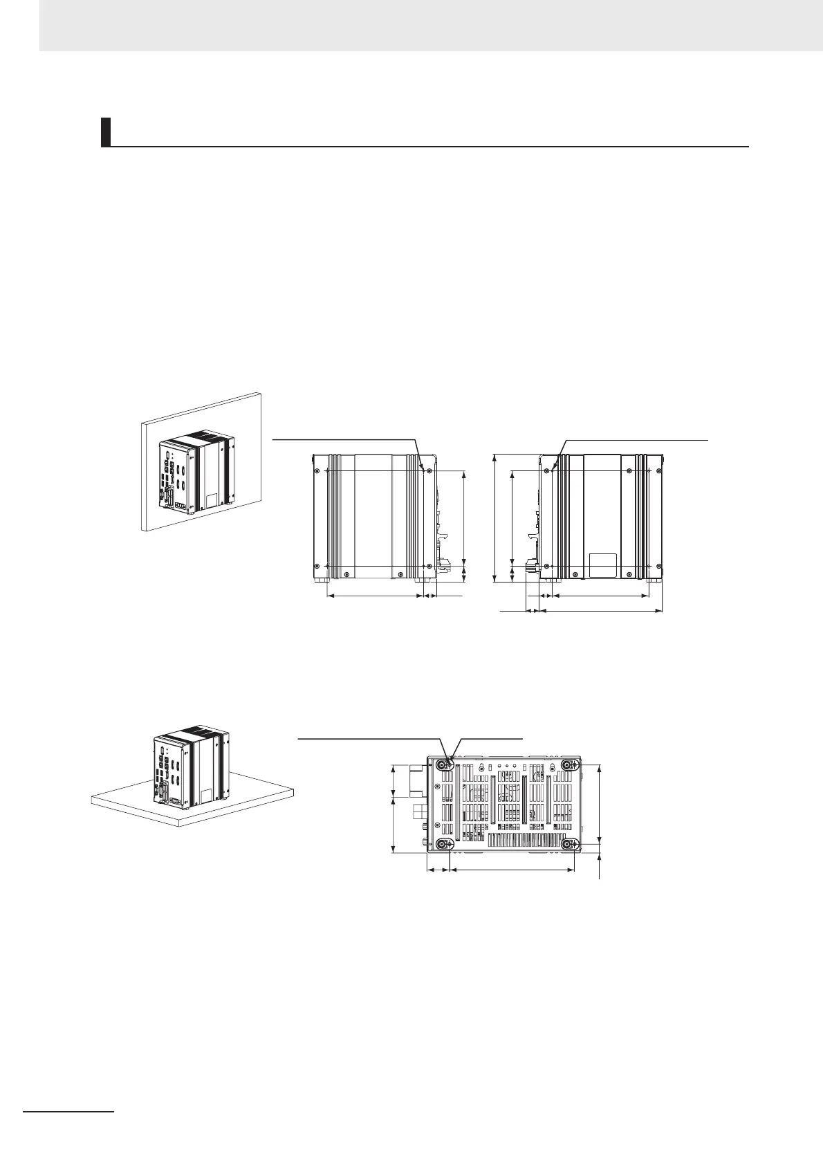
Side Mounting
Bottom Mounting
Mounting of FH-1000/FH-3000 Series
19.5
143
24
141
4-M4 depth 4.5 (mounting screw hole)
19.2
143
182.5
24
141
190
20.1
4-M4 depth 4.5 (mounting screw hole)
(Unit: mm)
• Left side • Right side
* Recommended tightening torque: 1.2 N•m to 1.3 N•m
* The tolerance is ±0.2 mm.
38.1
26.7
148.5
10.5
94
66.2
4-M3 depth 4.5 (mounting screw hole) Insulating leg: 4
• Bottom
(Unit: mm)
* Do not remove the Insulating leg. Fix the Insulating leg to secure the ventilation path.
* Recommended tightening torque: 0.54 N•m to 0.6 N•m
* The tolerance is ±0.2 mm.

 Loading...


