6 I/O Interface
6 - 58
Vision System FH/FZ5 series Hardware Setup Manual (Z366)
RS-232C interface is used in FH-1000, FH-3000, and FH-L series.
Prepare the suitable connector. Recommended connector is the following table.
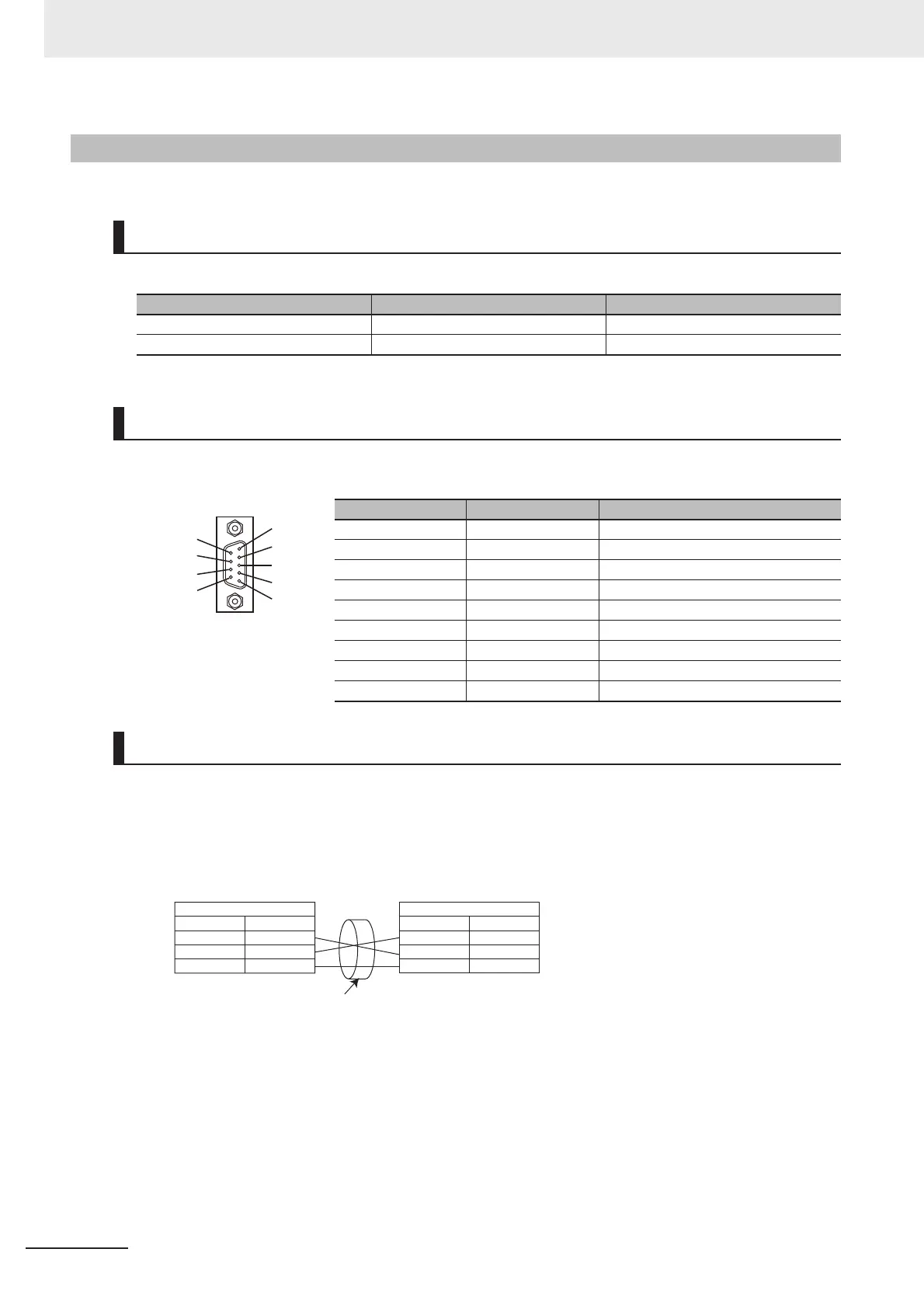
D-Sub9 Male type connector is used in Sensor Controller.
• Bundle each cable with SG (signal ground) as a twisted pair cable. Connect the bundled SG cables
with the connector on the Sensor Controller and the connector on the other device.
• Connect the communication cable shield to the RS-232C connector shell (FG) on the Sensor Con-
troller.
• The pin numbering will differ depending on type and model of the connected external device.
6-5-2 FH-1000, FH-3000, and FH-L Series
Input and output Connector
Manufacturer Model
Sockets OMRON Corporation XM3D-0921
Hood OMRON Corporation XM2S-0911
Pin Layout
Pin No. Signal name Function
1 NC Not connected
2 RD Data reception
3 SD Data transmission
4 NC Not connected
5 GND Signal ground
6 NC Not connected
7 NC Not connected
8 NC Not connected
9 NC Not connected
Wiring
5
4
3
2
1
9
8
7
6
Signal name
RD
SD
GND
Sensor Controller
Pin No.
2
3
5
Pin No.
External device to be connected
RS/CS control cannot be used
Signal name
RD*
*
*
SD
GND
Use a shielded cable.

 Loading...


