6 - 55
6 I/O Interface
Vision System FH/FZ5 series Hardware Setup Manual (Z366)
6-4 Ethernet Interface
6
6-4-4 FZ5-L Series
• Connect the LAN cable with a straight or cross cable.
• Use an STP (shielded twisted-pair) cable of category 5, 5e, or higher. Applicable EtherNet/IP com-
munications cables and connectors vary depending on the used baud rate.
• For 100Base-TX and 10Base-T, use an STP (shielded twisted-pair) cable of category 5 or higher. You
can use either a straight or cross cable.
• For 1000Base-T, use an STP (shielded twistedpair) cable (double shielding with aluminium tape and
braiding) of category 5e or higher.
• Electrical specifications: Conforming to IEEE 802.3 standards. Use RJ45 8-pin Modular Connector
(conforming to ISO 8877).
• When selecting a connector, confirm that it is applicable to the cable that will be used. Confirm the
following items: Conductor size, conductor type (solid wire or twisted wire), number of twisted pairs (2
or 4), outer diameter, etc.
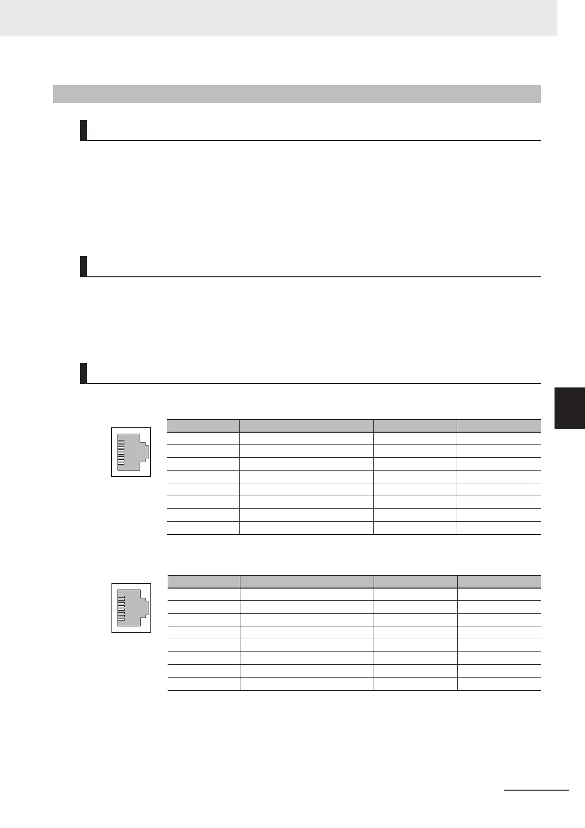
10Base-T and 100Base-TX
1000Base-T
6-4-4 FZ5-L Series
Cable
I/O Connector
Pin Layout
Connector pin Signal name Abbr. Signal direction
1 Transmission data + TD + Output
2 Transmission data - TD - Output
3 Reception data + RD + Input
4 Not used. --- ---
5 Not used. --- ---
6 Reception data - RD - Input
7 Not used. --- ---
8 Not used. --- ---
Connector pin Signal name Abbr. Signal direction
1 Communication data DA + BI_DA + Input/output
2 Communication data DA - BI_DA - Input/output
3 Communication data DB + BI_DB + Input/output
4 Communication data DC + BI_DC + Input/output
5 Communication data DC - BI_DC - Input/output
6 Communication data DB - BI_DB - Input/output
7 Communication data DD + BI_DD + Input/output
8 Communication data DD - BI_DD - Input/output

 Loading...


