6 I/O Interface
6 - 48
Vision System FH/FZ5 series Hardware Setup Manual (Z366)
Wring
• Connect both ends of the cable shield with the connector hood.
• Use the T568A wiring method as mentioned above.
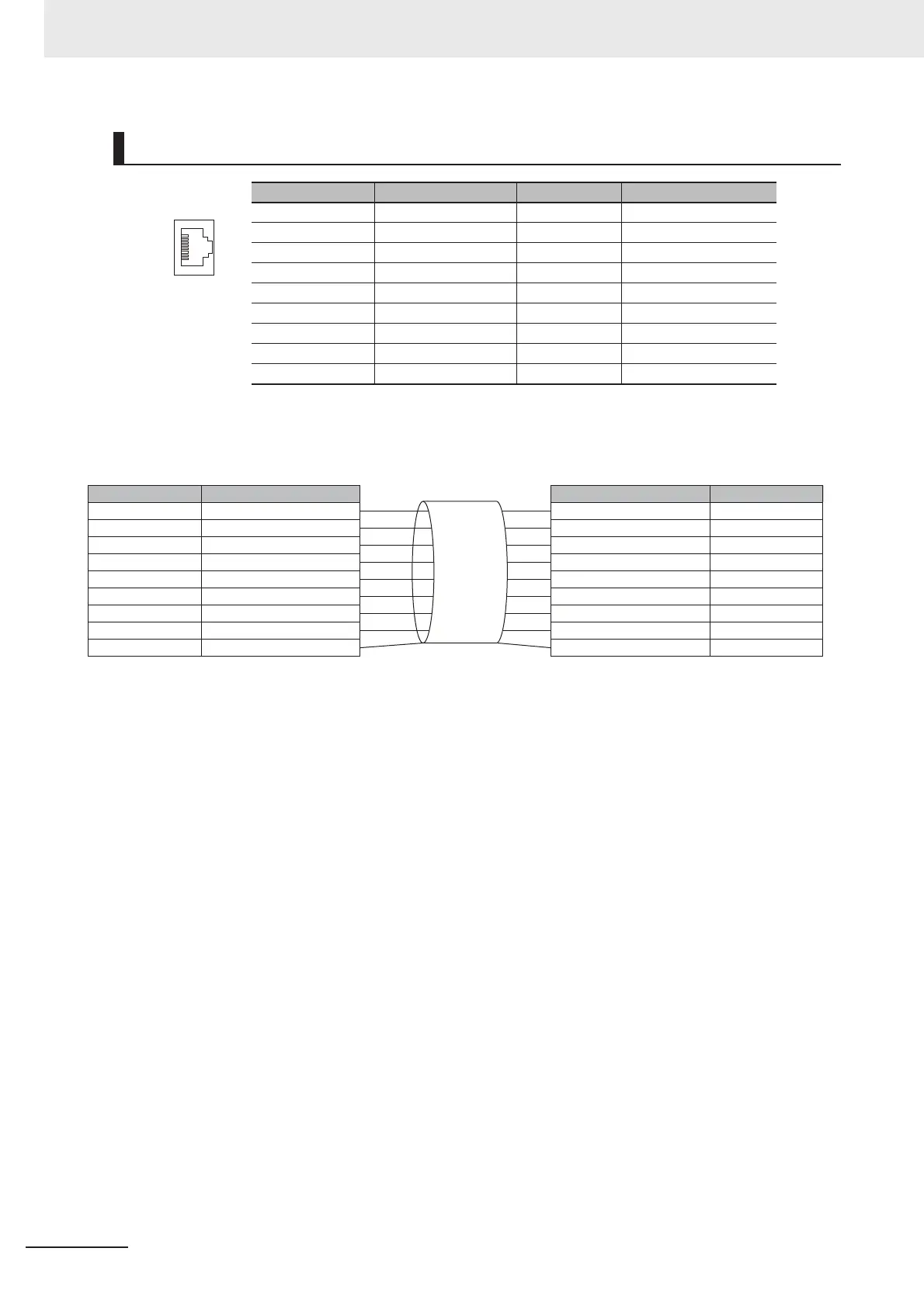
Pin Layout
Pin assignment Pin No. Signal name Abbreviation Signal direction
1 Transmission data + TD + Out
2 Transmission data - TD - Out
3 Reception data + RD + In
4 Not connected NC ---
5 Not connected NC ---
6 Reception data - RD - In
7 Not connected NC ---
8 Not connected NC ---
Connector hood Security ground FG ---
Pin No.
1
2
3
4
5
6
7
8
Connector hood
Pin No.
1
2
3
4
5
6
7
8
Connector hood
Wire color
White·Green
Green
White·Orange
Blue
White·Blue
Orange
White·Brown
Brown
Shielded cable
Wire color
White·Green
Green
White·Orange
Blue
White·Blue
Orange
White·Brown
Brown
Shielded cable

 Loading...


