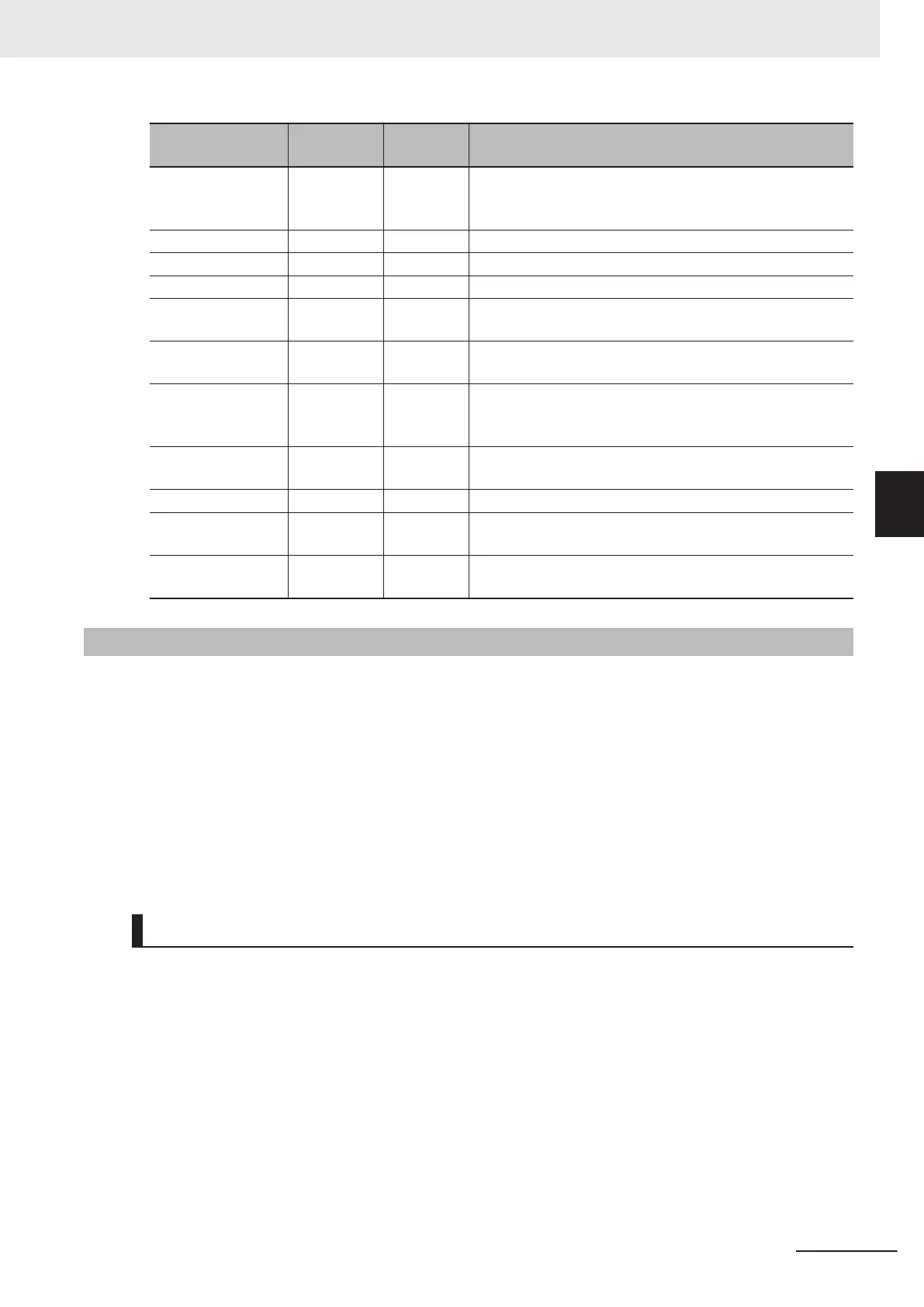
Name Model
Manufac-
turer
Description
EtherNet/IP Coupler
Unit
NX-EIC202 OMRON A Coupler Unit that supports EtherNet/IP.
This Unit can compose a Slave Terminal by connecting with
an NX Unit.
Safety CPU Unit
NX-SL3300 OMRON A Unit that runs safety programs.
Safety Input Unit NX-SIH400 OMRON A Unit to be connected with safety input devices.
Safety Output Unit NX-SOD400 OMRON A Unit to be connected with safety output devices.
Safety Light Curtain F3SG OMRON A photoelectric safety sensor. This sensor detects human
entry to hazardous area.
Safety Door Switch D40A OMRON A non-contact safety door switch. This switch detects open
and close of the entrance door to hazardous area.
Reset Switch A22-H
£-10M
OMRON A reset switch. This switch is used to manually recover the
equipment from the stop state after the safety function oper-
ated.
Emergency Stop
Pushbutton Switch
A22E OMRON An emergency stop switch.
Safety Relay G7SA OMRON A safety relay.
Unit Power Supply S8VK OMRON A 24 VDC power supply. This control power supply is for the
EtherNet/IP Coupler Units and the NX Units.
I/O Power Supply S8VK OMRON A 24 VDC power supply. This power supply is for the I/O cir-
cuits of the NX Units and the connected external devices.
A-1-6
Installation and Wiring
This section describes the installation and wiring related to the safety functions for the pick-and-place
equipment.
The NX Unit configuration of the EtherNet/IP Slave Terminal and the wiring diagram of the safety devi-
ces are described in this guide.
Refer to the following manual for details on installing and wiring the actual devices.
• NX-series Safety Control Unit User’s Manual (Cat. No. Z930)
• NX-series EtherNet/IP Coupler Unit User’s Manual (Cat. No. W536)
• eCobra 600 and 800 Robot with EtherCAT User’s Guide (Cat. No. I653)
• T20 Pendant User's Guide (Cat. No. I601)
NX Unit Configuration
Compose the EtherNet/IP Slave Terminal by the connection order shown in the figure below.
Appendices
A-7
NJ-series Robot Integrated System Startup Guide (O049)
A-1 Designing Example of the Safety Functions for the Pick-and-
place Equipment
A
A-1-6 Installation and Wiring
 Loading...


