2-2
Installing and Wiring the System
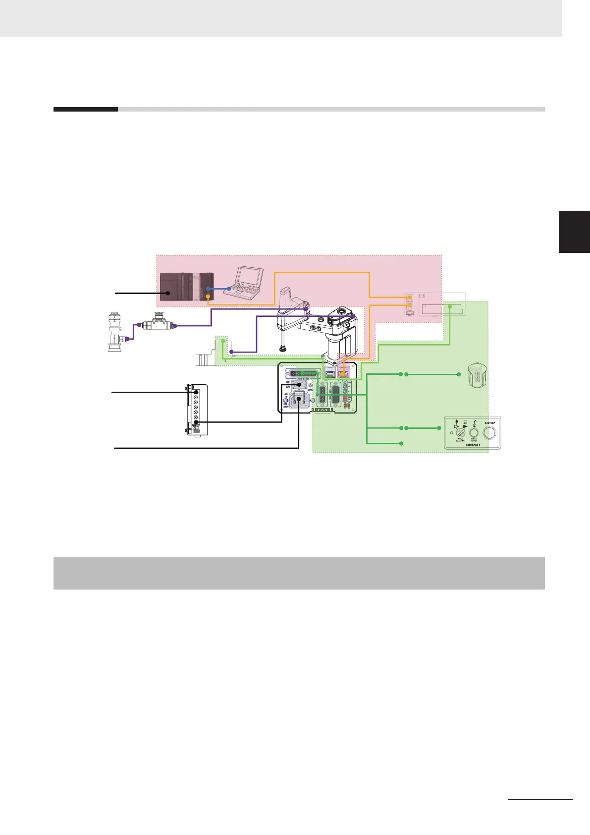
In the system configuration, you must wire the signal lines covered in the colored areas in the figure
below and set the node address of the robot.
• Wiring between the Robot Integrated CPU Unit (A) and the EtherCAT Digital I/O Terminal (F)
• Wiring between the EtherCAT Digital I/O Terminal (F) and the robot (C)
• Wiring between the Robot Integrated CPU Unit (A) and the computer (E)
• Wiring between the robot (C) and the T20 pendant (I)
• Wiring between the robot (C) and the front panel (K)
• Wiring between the EtherCAT Digital I/O Terminal (F) and the solenoid valve (Q)
(P)
(G)
(C)
(B)
(A)
(S)
(E)
(D)
(R)
(O)
(N)
(M)
(Q)
(F)
(H)
(J)
(I)
(L)
(K)
100 to 240 VAC
85 to 264VAC, 6.5A
Single phase, AC200 to 240VAC, 10A
XMCP
XFP
XUSR
*1
Refer to 1-2 System Configuration for Static Pick-and-place Equipment on page 1-3 for information on
the parts used in the system configuration.
Refer to the manual for the specific product for details on power lines not covered in the colored area
as well as for ducting from the robot.
2-2-1
Wiring the Robot Integrated CPU Unit and the EtherCAT Digital
I/O Terminal
Y
ou must wire the Robot Integrated CPU Unit and the EtherCAT Digital I/O Terminal.
1 Connect the EtherCAT port of the Robot Integrated CPU Unit and the EtherCAT IN port of the
EtherCA
T Digital I/O T
erminal with an Ethernet cable.
2 Before You Begin
2-3
NJ-series Robot Integrated System Startup Guide (O049)
2-2 Installing and Wiring the System
2
2-2-1 Wiring the Robot Integrated CPU Unit and the EtherCAT Digital I/O Terminal
 Loading...


