Item Specification
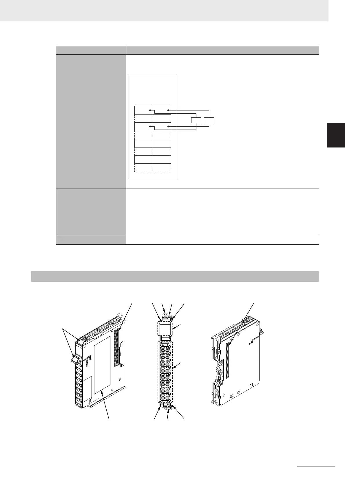
Terminal connection dia-
gram
So0 to So3: Safety output terminals
IOG: I/O power supply 0 V
So0
Safety Output Unit
NX-SOD400
A1 B1
A8 B8
So1
L L
IOG IOG
So2 So3
IOG IOG
Refer to 4-3-2 Safety Output Function on page 4 - 32 for details.
Installation orientation
and restrictions
Installation orientation:
• Connected to a CPU Unit or a Communication Control Unit
*1
Possible in the upright installation orientation.
• Connected to a Communications Coupler Unit
Six possible orientations.
Restriction: None.
Protective functions Overvoltage protection circuit and short detection
*1. Only NX102 CPU Units and Communication Control Units can be connected. NX1P2 CPU Units cannot be
connected.
2-3-2
Part Names and Functions
This section provides the names and functions of the parts of the Safety Output Unit.
(C)
(D)
(H)
(G)
(F)
(C)
(A)
(E)
(C)(E)
(C)
(B)
(B)
2 Specifications
2 - 35
NX-series Safety Control Unit User's Manual (Z930)
2-3 Safety Output Unit
2
2-3-2 Part Names and Functions
 Loading...


