Item Specification
Installation orientation and re-
strictions
Installation orientation:
• Connected to a CPU Unit or a Communication Control Unit
*1
Possible in the upright installation orientation.
• Connected to a Communications Coupler Unit
Six possible orientations.
Restriction: Maximum ambient temperature is 50°C for any orientation oth-
er than upright installation.
Protective functions Overvoltage protection circuit and short detection (test outputs)
*1. Only NX102 CPU Units and Communication Control Units can be connected. NX1P2 CPU Units cannot be
connected.
2-2-2
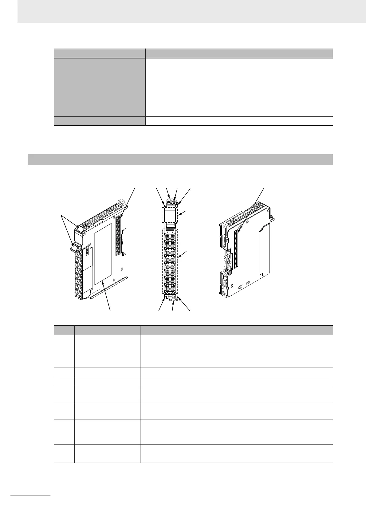
Part Names and Functions
This section provides the names and functions of the parts of the Safety Input Unit.
(C)
(D)
(H)
(G)
(F)
(C)
(A)
(E)
(C)(E)
(C)
(B)
(B)
Letter Name Function
(A) Marker attachment loca-
tion
The locations where markers are attached. The markers made by OMRON
are installed for the factory setting. Commercially available markers can also
be installed.
Refer to 3-1-2 Attaching Markers on page 3 - 4.
(B) NX bus connector This is the NX-series bus connector.
(C) Unit hookup guides These guides are used to connect two Units.
(D) DIN Track mounting
hooks
These hooks are used to mount the NX Unit to a DIN Track.
(E) Protrusions for removing
the Unit
The protrusions to hold when removing the Unit.
(F) Indicators The indicators show the current operating status of the Safety Input Unit or
signal input status.
Refer to 2-2-3 Indicators on page 2 - 24.
(G) Terminal block The terminal block is used to connect external devices.
(H) Unit specifications The specifications of the Safety Input Unit are given here.
2 Specifications
2 - 22
NX-series Safety Control Unit User's Manual (Z930)
 Loading...


