2-90
D CN2 Connectors Used (6P)
Receptacle at Servo Driver 53460-0611 (Molex Japan Co., Ltd.)
Cable plug 55100-0670 (Molex Japan Co., Ltd.)
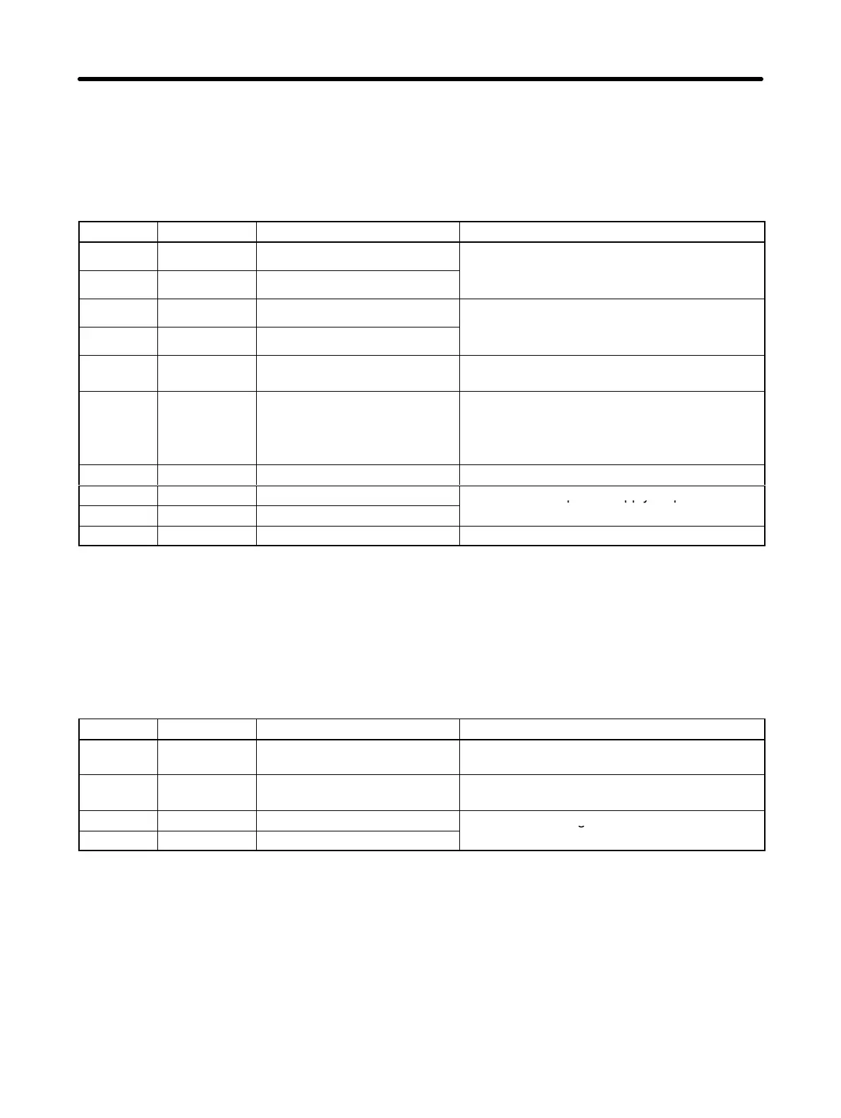
2-4-6 Parameter Unit Input Specifications (CN3)
Pin No. Symbol Signal name Function/Interface
1, 8 TXD+ Transmission data +
This is data transmitted to a Parameter Unit (or
2, 9 TXD– Transmission data –
.
Line receiver input
3, 10 RXD+ Reception data +
This is data received from a Parameter Unit (or
4, 6 RXD– Reception data –
.
Line receiver input
5 PRMU Unit switching This is the switching terminal for a Parameter
Unit or personal computer.
7 RT Termination resistance
terminal
This is the termination resistance terminal for
the line receiver.
6-pin connection for RS-422 communications
(final Servo Driver only).
11, 12 – (Not used.) (Do not connect.)
13 +5V +5 V output
This is the +5-V power supply output to the
14 GND Ground
Parameter Unit.
Shell FG Shielded ground Cable shielded ground
D CN3 Connectors Used (14P)
Receptacle at Servo Driver 10214-52AJL (Sumitomo 3M)
Cable plug with solder 10114-3000VE (Sumitomo 3M)
Cable case 10314-50A0-008 (Sumitomo 3M)
2-4-7 Monitor Output Connector Specifications (CN5)
Pin No. Symbol Signal name Function/Interface
1 MM Analog Monitor 2 Default setting: Speed monitor, 1 V per
1,000 r/min (Can be changed by Pn003.1.)
2 AM Analog Monitor 1 Default setting: Current monitor, 1 V / rated
torque (Can be changed by Pn003.0.)
3 GND Analog Monitor Ground
Grounds for analog monitors 1 and 2
4 GND Analog Monitor Ground
D CN5 Connectors Used (4P)
Pin header at Servo Driver DF11-4DP-2DS (Hirose Electric )
Cable connector socket DF11-4DS-2C (Hirose Electric )
Cable connector contact DF11-2428SCF (Hirose Electric )
D Monitored Items and Scaling Changes
Monitored items can be changed by means of Pn003 (function selection application switch 3). It is also
possible to change the scaling and adjust the output voltage offset in the system check mode.
Standard Models and Specifications Chapter 2

 Loading...


