2-131
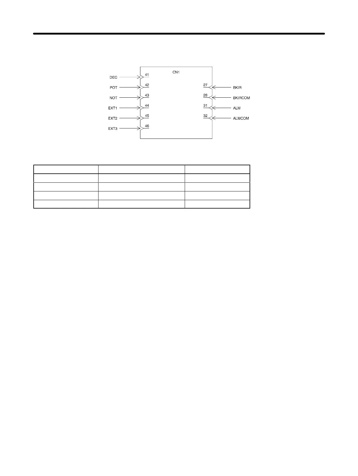
Note 7. Use the Terminal Block only after allocating Servo Driver signals to pins. The following param-
eters are set when wiring as described in the above wiring example.
Input signal Output signal
I/O Signal (CN1) Parameter Settings
Parameter No. Name Setting
Pn50A Input Signal Selection 1 2881
Pn50B Input Signal Selection 2 8883
Pn511 Input Signal Selection 5 6541
Pn50F Output Signal Selection 2 0200
2-6-2 Motor Cable Specifications
The motor cable is used to connect the Servo Driver and Servomotor. Select the appropriate cable for
the Servomotor. The maximum distance between Servo Driver and Servomotor is 50 m.
Note Use a Robot Cable if the cable needs to bend.
D Bend Resistance of Robot Cables
Robot Cables use wire that has a bending life of 20 million times when used at the minimum bending
radius (R) or greater under the following conditions.
Note 1. The bending resistance data was compiled under test conditions and must be used as a guide
only. An extra margin must always be allowed.
Note 2. The life expectancy is the number of uses without cracks or damage to the sheath that would
affect performance while current is applied to the wire conductor. This value does not apply to
cut shield strands.
Note 3. If Robot Cables are used at a bending radius smaller than the minimum bending radius, me-
chanical malfunctions, ground faults, and other problems may occur due to insulation break-
down. Contact your OMRON representative if you need to use a Robot Cable with a bending
radius smaller than the minimum bending radius.
Standard Models and Specifications Chapter 2

 Loading...


