4-127
• These monitor values can also be cleared (i.e., set to zero) in Monitor Mode.
Feedback pulse
counter
Feedback pulse counter monitor
value (upper 16-bit part, dis-
played as “H.jjjj“)
Feedback pulse counter monitor
value (lower16-bit part, displayed
as “L.jjjj“)
1 s min.
1 s min.
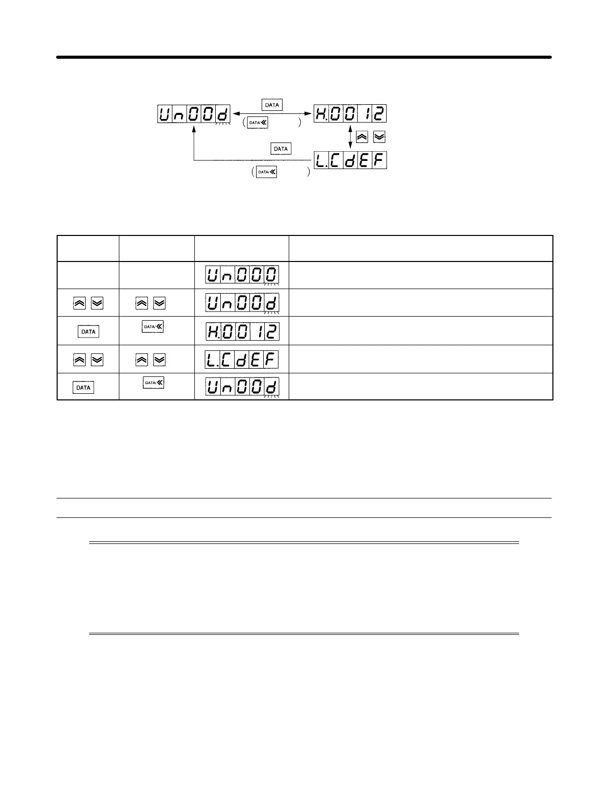
Operating Procedure Example: Feedback Pulse Counter (Un.00d) Monitor Value
Display
PR02W
operation
Front panel
key operation
Display Explanation
(Monitor Mode)
Set monitor No. Un004 using the Up or Down Key. (See
note 1.)
(1 s min.)
Press the DATA Key (front panel: DATA Key for 1 s min.)
to display upper 4 digits (16-bit part) as H.jjjj
Press the Up or Down Key to display lower 4 digits
(16-bit part) as L.jjjj
(1 s min.)
Press the DATA Key (front panel: DATA Key for 1 s min.)
to return to monitor number display.
Note 1. Digits that can be manipulated will flash.
Note 2. Press Up and Down Keys simultaneously when the monitor value is displayed (i.e.,
“H.jjjj“ or “L.jjjj“ is displayed) to clear the counter (i.e., reset to H.0000 or L.0000).
4-10 Using Monitor Output
OMNUC W-series AC Servo Drivers output in analog form the Servomotor rotation
speed, torque command, position difference, and other proportional voltage amounts
from the Analog Monitor Output Connector (CN5). This function can be used in situa-
tions such as making fine gain adjustments or when a meter is attached to the control
panel. Select the monitor items using user parameters Pn003.0 and Pn003.1. Also, use
Fn00C and Fn00d in System Check Mode to adjust the offset and change the scaling.
Operation Chapter 4

 Loading...


