2-67
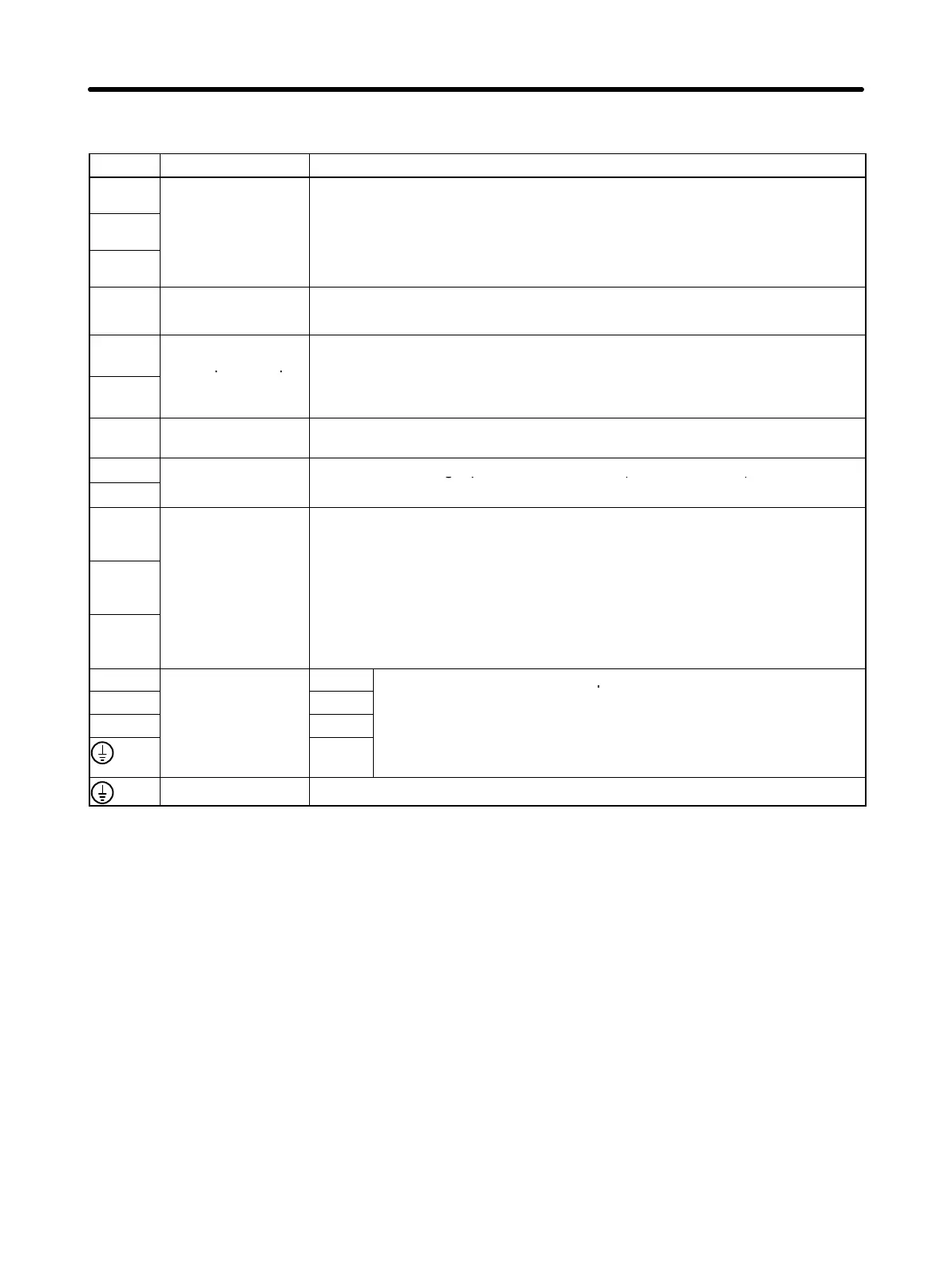
2-4-3 Terminal Block Specifications
Signal Function Condition
L1
Main circuits pow-
er su
l
in
ut
R88D-WTjH (30 to 400 W):
Sin
le-
hase 200/230 V AC
170 to 253 V AC
50/60 Hz
L2
Single phase 200/230 V AC (170 to 253 V AC) 50/60 Hz
R88D-WTjH (500 W to 6 kW):
Three-phase 200/230 V AC (170 to 253 V AC) 50/60 Hz
L3
Three phase 200/230 V AC (170 to 253 V AC) 50/60 Hz
R88D-WTjHL (30 to 200 W):
Single-phase 100/115 V AC (85 to 127 V AC) 50/60 Hz
+ Main circuit DC
output (Forward)
Do not connect anything. This terminal is for the R88D-WT60H to
R88D-WT150H.
+1
DC Reactor termi-
nal for power sup-
Normally short-circuit between +1 and +2.
If harmonic control measures are re
uired
connect a DC Reactor between
+2
ply harmonic con-
trol
If harmonic control measures are required
,
connect a DC Reactor between
+1 and +2. (This terminal is not provided in R88D-WT60H to R88D-WT150H
models.)
– Main circuit DC
output (Reverse)
Do not connect anything.
L1C
Control circuits
R88D-WTjH: Single-phase 200/230 V AC (170 to 253 V AC) 50/60 Hz
L2C
power supply input
R88D-WTjHL: Single-phase 100/115 V AC (85 to 127 V AC) 50/60 Hz
B1
External regenera-
tion resistance
connection termi-
30 to 400 W: This terminal does not normally need to be connected. If regen-
erative energy is high, connect an External Regeneration Resistor between
B1 and B2.
B2
nal
.
500 W to 5 kW: Short-circuit between B2 and B3. If regenerative energy is
high, remove the short bar between B2 and B3 and connect an External Re-
generation Resistor between B1 and B2
B3
genera
on
es
s
or
e
ween
an
.
6 to 15 kW: Connect an External Regeneration Resistance Unit between B1
and B2.
U
Servomotor con-
Red
These are the terminals for outputs to the Servomotor. Be sure to
V
nection terminals
White
wire these terminals correctly.
W Black
Green/
Yellow
Frame ground This is the ground terminal. Ground to a minimum of 100 Ω (class-3).
Standard Models and Specifications Chapter 2

 Loading...


