4-128
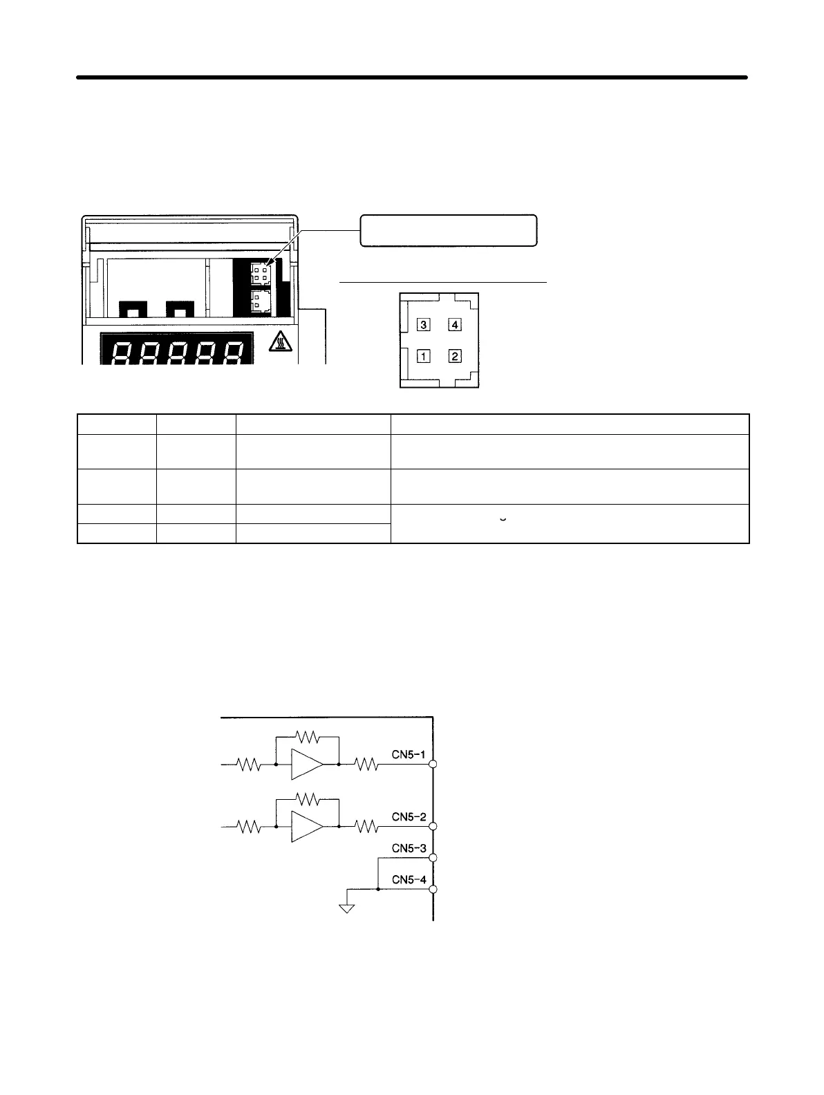
H Analog Monitor Output Connector (CN5)
• The Analog Monitor Output Connector (CN5) is located inside the top cover of the Servo Driver.
Note There is no top cover on models R88D-WT60H to R88D-WT150H (6 to 15 kW). Instead, CN5 is to
the right of the display and settings area.
Analog Monitor Output
Connector (CN5)
CN5 pin distribution (front panel view)
Driver pin header: DF11-4DP-2DS
Cable connector socket: DF11-4DS-2C
Cable connector contact: DF11-2428SCF
(Manufactured by Hirose.)
View with upper cover open
Pin No. Symbol Name Function and interface
1 NM Analog monitor 2 Default setting: Speed monitor 1 V / 1000 r/min. (change
using Pn003.1)
2 AM Analog monitor 1 Default setting: Current monitor 1 V / rated torque
(change using Pn003.0)
3 GND Analog monitor ground
Ground for analog monitors 1 and 2
4 GND Analog monitor ground
Note 1. Displays status with no change to scaling.
Note 2. Maximum output voltage is 8 V. Exceeding this value may result in an abnormal output.
Note 3. Output accuracy is approximately 15%.
H Analog Monitor Output Circuit
Servo Driver
NM (analog monitor 2)
AM (analog monitor 1)
GND (analog monitor ground)
GND (analog monitor ground)
47 Ω
47 Ω
Operation Chapter 4

 Loading...


