3-29
conditions were stipulated when EMC Directive approval was obtained for the W Series.
They will be affected by the installation and wiring conditions resulting from the con-
nected devices and wiring when the W Series is built into the system. Therefore, the en-
tire system must be checked for conformity.
The following conditions must be satisfied in order to conform to the EC Directives.
• The Servo Driver must be mounted in a metal case (control box). (It is not necessary to mount the
Servomotor in a metal box.)
• Noise filters and surge absorbers must be inserted in power supply lines.
• Shielded cable must be used for I/O signal cables and encoder cables. (Use tinned soft steel wire.)
• Cables leading out from the control box must be enclosed within metal ducts or conduits with blades.
(It is not necessary to enclose the 30-cm power cable, encoder cable, or connectors in a metal duct or
conduit.)
• Ferrite cores must be installed for cables with braided shields, and the shield must be directly
grounded to a ground plate.
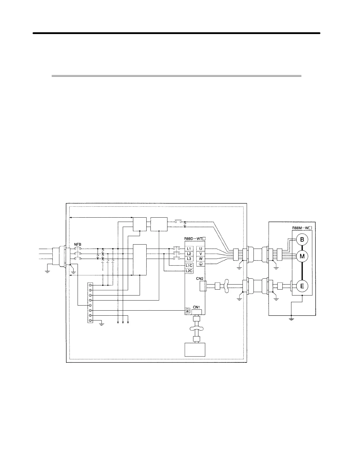
H Wiring Method
AC
power
supply
Metal
duct or
conduit
Control box
2 m max.
Noise
filter
Brake
power
supply
Surge
absorber
Ground
plate
Controller
power
supply
Controller
Clamp
Ferrite core
Clamp
Metal
duct or
conduit
Motor built-in device
Ferrite
core
Contactor
Class-3
ground (to
100 Ω or less)
Ferrite
core
Ferrite
core
Ferrite
core
Ferrite core
2 m max.
Noise
filter
(See note 3.)
Note 1. Make 1.5 turns for the ferrite core’s cable winding.
Note 2. Peel the insulation off the cable at the clamp, and directly connect the shield to the metal plate.
Note 3. For single-phase power supply input models (R88D-WTA3Hj to R88D-WT04H), the main-
circuit power supply input terminals will be L1 and L2.
• Ground the motor’s frame to the machine ground when the motor is on a movable shaft.
• Use a grounding plate for the frame ground for each Unit, as shown in the above diagrams, and ground
to a single point.
System Design and Installation
Chapter 3

 Loading...


