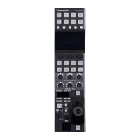
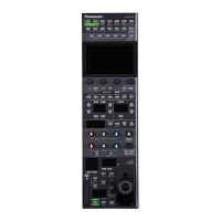
Front panel 5
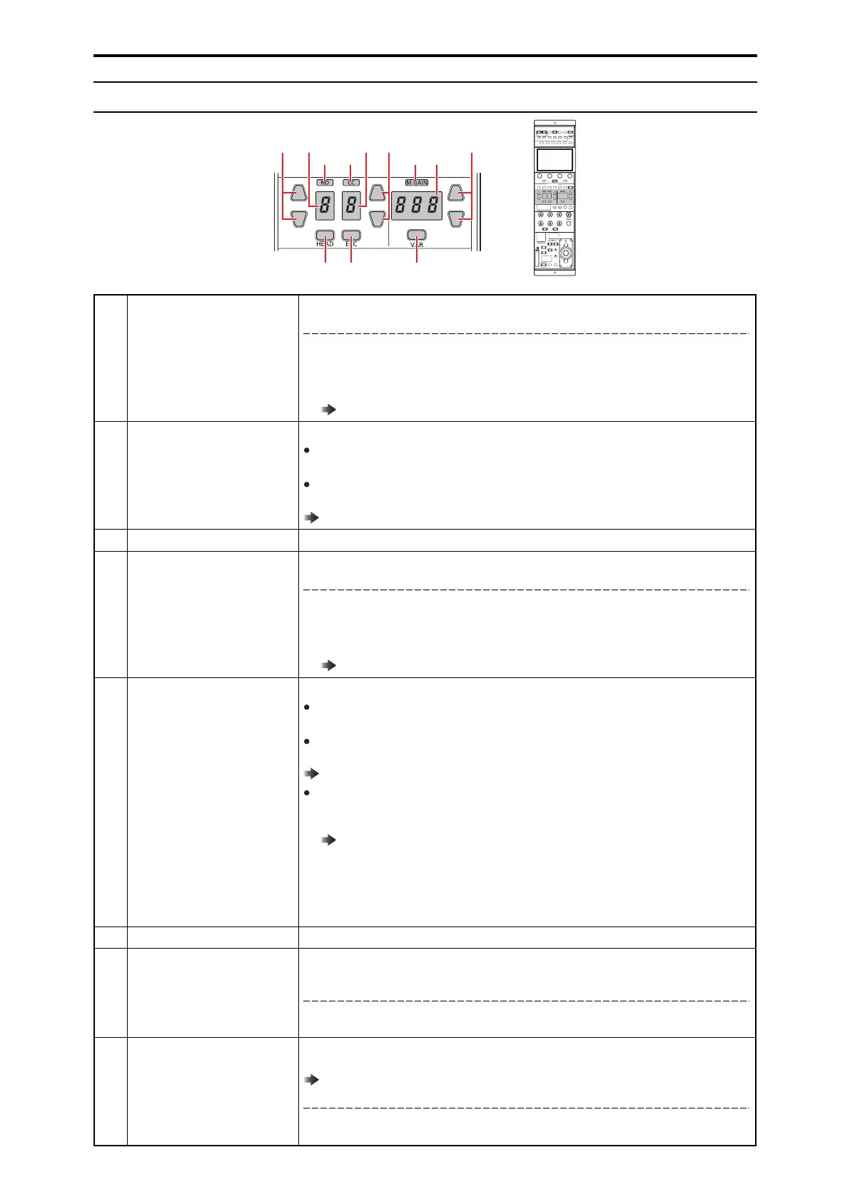
1 [ND] indicator This indicator indicates the ND filter setting status.
Status displays
Lit green: Standard position set in the ROP menu.
Lit Orange: Updated from the standard position set in the ROP menu.
n The standard position of the ND filter can be set in [ROP SETTING] > [STD POSITION
ND] in the ROP menu.
“STD POSITION ND” (see page 112)
2 [ND] setting buttons Use the up and down buttons to select the ND filter setting.
When [HEAD] button off
Changes the ND filter setting.
When [HEAD] button lit
Only displays the ND filter position. (Switching is not possible.)
“ND filter” (see page 39)
3 [ND] display This displays the ND filter position.
4 [CC] indicator This indicator indicates the CC filter setting status.
Status displays
Lit green: Standard position set in the ROP menu.
Lit Orange: Updated from the standard position set in the ROP menu.
n The standard position of the CC filter can be set in [ROP SETTING] > [STD POSITION
CC] in the ROP menu.
“STD POSITION CC” (see page 112)
5 [CC] setting buttons Use the up and down buttons to select the CC filter setting.
When [HEAD] button off
Changes the CC filter setting.
When [HEAD] button lit
Only displays the CC filter position. (Switching is not possible.)
“CC filter” (see page 40)
When [ECC] button lit
When [ROP SETTING] > [ECC BTN CTRL] is set to “VAR” in the ROP menu, you can con-
figure the [ECC] > [COLOR TEMP] values in the ROP menu.
“COLOR TEMP” (see page 74)
When [ROP SETTING] > [ECC BTN CTRL] is set to “MEM” in the ROP menu, the setting
values registered to memory presets A to E in the [ECC] menu are recalled.
The recalled memory preset appears on the [CC] display.
In this state, the display will remain as the recalled memory preset, even if the [ECC] >
[COLOR TEMP] settings in the ROP menu are changed.
6 [CC] display This displays the CC filter position.
7 [HEAD] button Use this button to enable filter control on the camera side.
The [HEAD] button also lights when the camera's [FILTER LOCAL] switch is pressed and lit.
Status displays
On: Filter control enabled on the camera side
Off: Filter control enabled on the ROP (this unit) side
8 [ECC] button When this button is lit, [ECC] > [COLOR TEMP SW] in the ROP menu can be enabled or dis-
abled.
“Color temperature (ECC)” (see page 41)
Status displays
On: ECC operation ([COLOR TEMP SW] enabled)
Off: CC filter operation ([COLOR TEMP SW] disabled)
- 25 -
Parts and their functions
 Loading...