5.3
BODY / STEERING / SUSPENSION
5
9923523 - 2012 RANGER RZR 570 Service Manual
© Copyright 2011 Polaris Sales Inc.
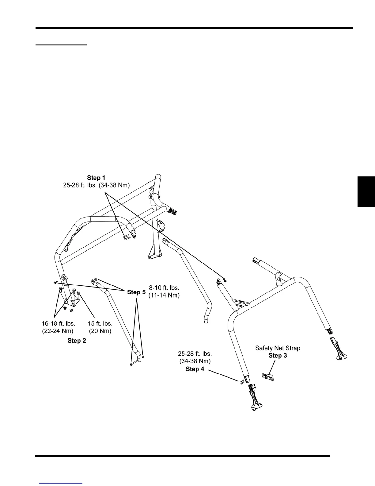
CAB FRAME
Assembly / Removal
NOTE: Finger tight en all co mponents until cab
frame is c ompletely ass embled on veh icle, t hen
tighten to specifications listed.
1. Assemble the rear cab frame and the front cab frame
a
t the coupler joints and secure with four (3/8-16 x 1
1/4) screws and (3/8-16 Nyloc) nuts. Tighten screws
to 25-28 ft. lbs. (34-38 Nm).
2. Place the assembled cab frame onto the vehicle and
a
lign the rear mount holes. Fasten the rear cab frame
brackets to vehicle with four (5/16-18) bolts and (5/16-
18) nuts. Tighten bolts to 16-18 ft. lb s. (22-24 Nm).
Fasten the two se lf-tapping screws to the rear inner
portion of the bracket on each side. Tighten screws to
15 ft. lbs. (20 Nm).
3. Place the stra ps fro m the sa fety ne t over th e fro nt
co
upler posts.
4. Fasten the front of the cab frame to the base brackets
a
nd secure with four (3/8-16 x 1 1/4) screws and (3/
8-16 Nyloc) nuts. Tighten screws to 25-28 ft. lbs. (34-
38 Nm).
5. Attach side bars to cab frame using M6 screws and
n
uts on top and M8 screws and nuts on the bottom.
Tighten to 8-10 ft. lbs. (10.8-13.5 Nm).
6. To r emove the ca b fra me, r everse th e a ssembly
pr
ocedure (steps 1-5).
 Loading...