Raisecom Technology Co., Ltd
22
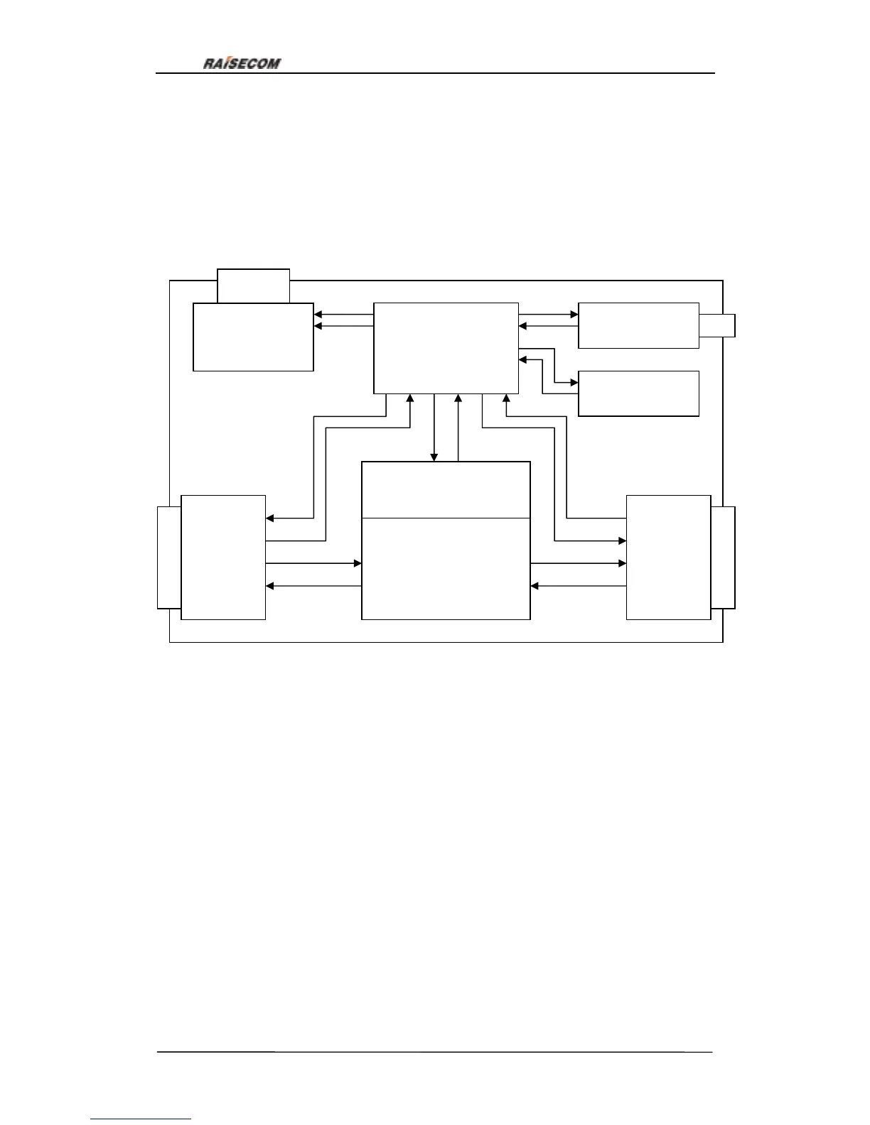
6. Structure and indicator lights
6.1. Fundamental structure:
Fundamental structure of RC3000 is as follows:
RC3000 can multiplex or demultiplex local voice channels or data to any time slots (time
slot 0 is not included) of RC7850’s 4 E1 through cross-matrix, the following is exact
explanations:
Line-board interface module: interface of up-link data channel, E1 or optical interface.
User-board interface module: user interface for data or voice access.
RC7850 module: cross connect the user information to up-link interface or up-link data
to user interface through cross-matrix.
Memory module: save all kinds of user configuration including work status and cross
information.
Network management channel: a management channel for PC.
System information & alarm information display module: provide our users present
system status and alarm information; meanwhile the buzzer will buzz so that user can
System
information &

 Loading...