Raisecom Technology Co., Ltd
40
Indicatore lights are all green:
TD: V35 data Tx indicator light
RD: V35 data Rx indicator light
LP_STA: loop indicator light. ON there is local loop
PAT_OK: In normal work status is OFF.
Do the RCR check: ON normal
OFF abnormal
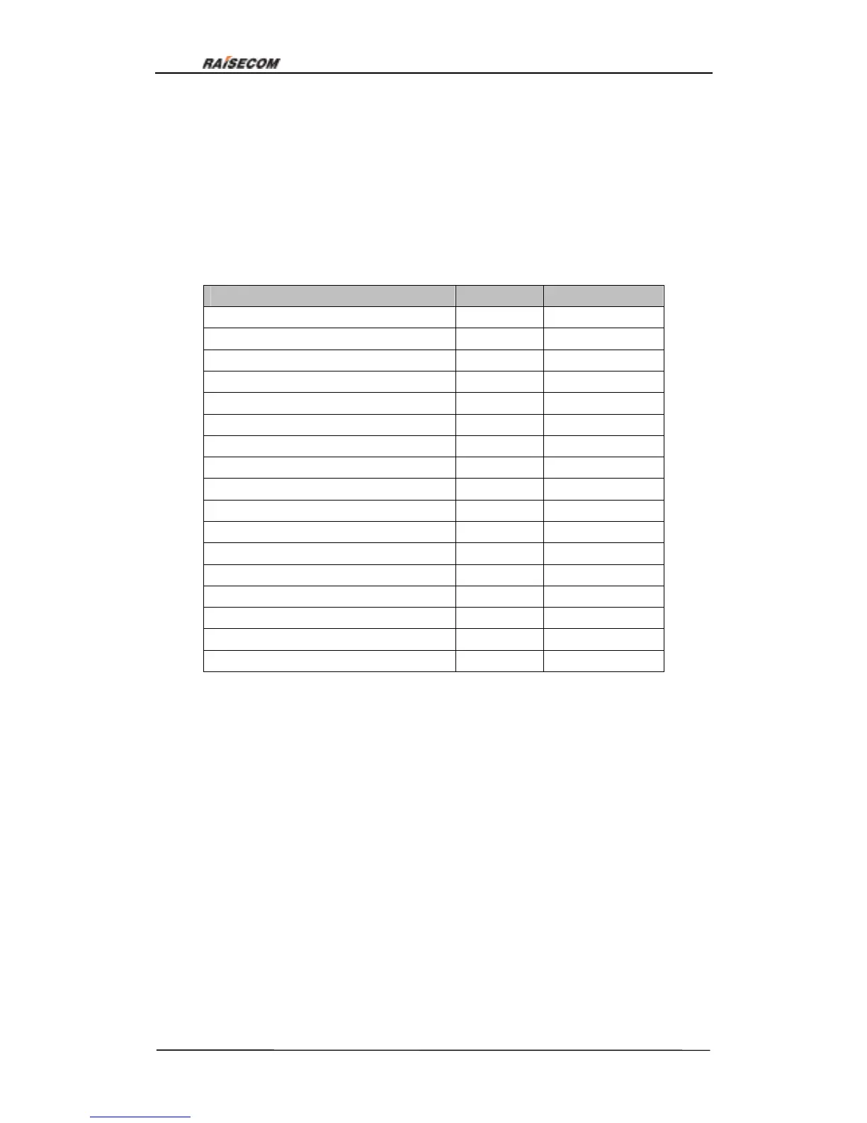
Interface definition:
Name Input/output Pin number
Chassis Ground — CGND - 1
Signal Ground — GND - 7
Receive Data (A) — RD(A) O 3
Receive Data (B) — RD(B) O 21
Receive Timing (A) — RCK(A) O 17
Receive Timing (B) — RCK(B) O 25
Send Data (A) — TD(A) I 2
Send Data (B) — TD(B) I 11
Send Timing (A) — TCK(A) O 15
Send Timing (B) — TCK(B) O 23
Terminal Timing (A) — SCTE(A) I 24
Terminal Timing (B) — SCTE(B) I 16
Request to Send — RTS I 4
Clear to Send — CTS O 5
Data Set Ready — DSR O 6
Data Carrier Detect — DCD O 8
Data Terminal Ready — DTR I 20
Note:I—input; O—output
7.7.3. V35 data card configuration explanation:
V35 user-board has many functions: plenty test methods, loop, phase adjustment and
etc. Both Hyper Terminal and network management can configure the following
commands:
a. Configuration of user card time slot; b. Phase of Rx data; c. Phase of Tx data; d.
Choose the data channel;
e. Loop configuration f. Error bit test; g. Auto adjustment of Tx data phase; h. Auto
adjustment of Rx data phase;
Please refer to Appendix A How to use Hyper Terminal to configure RC3000

 Loading...