Raisecom Technology Co., Ltd
24
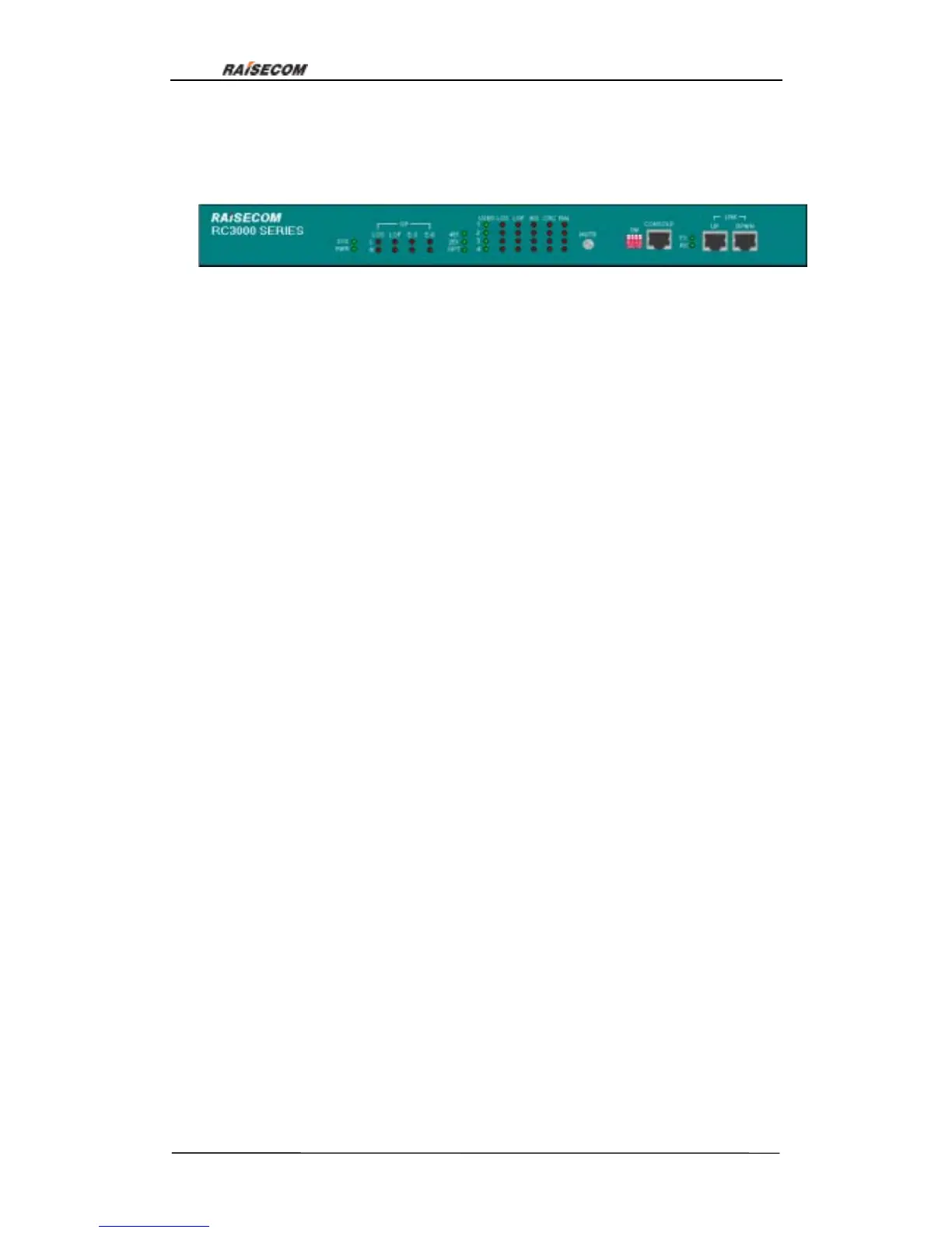
6.2. Front panel explanation:
Front view:
6.2.1. Globle indicator lights:
SYS(green): Indicates system work status. Flicking: system works normal. ON: 1 CUP
works abnormal; 2 system configuration error or the following problems:
1.User-board communicates abnormally
2.Temperature sensor works abnormally
3.Fan does not work
4.Time slots configuration error
OFF: CPU works abnormally
PWR(green): OFF system is not powered on
TX(green): ON serial interface is transmitting data
RX(green): ON serial interface is receiving data
6.2.2. Indicator lights of line-board:
4E1(green): ON line-board is 4E1 interface card
2E1(green): ON line-board is 2E1 interface card
OPT(green): ON line-board is optical interface card
Note: only one of the three lights can be ON, otherwise there is system error.
6.2.3. Optical interface alarm indicator lights:
Optical interface alarm indicator lights form a matrix, L and R indicate local and remote,
OP(LOS,LOF , E-3, E-6)indicate alarms:
L OP LOS(red): Loss of signal at local
L OP LOF(red): Loss of frame at local
L E1 E-3(red): Alarm when bit error ratio is more than 10
-3
/s at local
L E1 E-6(red): Alarm when bit error ratio is more than 10
-6
/s at local
R OP LOS(red): Loss of signal at remote
R OP LOF(red): Loss of frame at remote
Figure 17

 Loading...