Removing the Covers
SM 3-13 J007/J010/J011
J007/J010/
J011
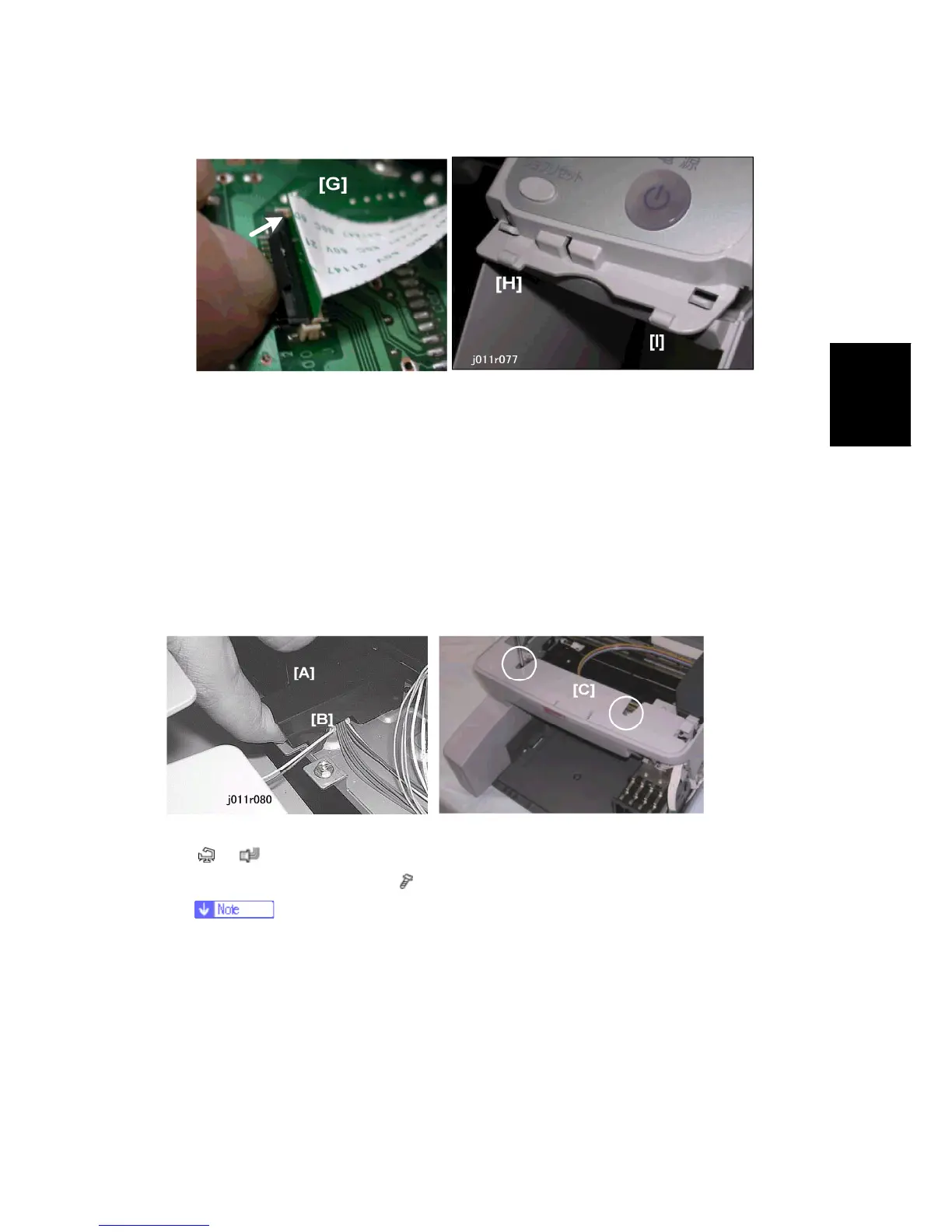
9. Push the latch [G] of the FFC connector away from the board to release the FFC.
10. Carefully separate the tabs and slots [H] and [I] to disconnect the operation
panel from the cover
Reinstallation
To reconnect the FFC:
Pull the FFC release away from the PCB.
Insert the tip of the FFC into the slot with the GREEN side up.
Push the FFC release toward the PCB to lock the FFC in place.
3.3.7 FRONT COVER
1. Remove the connector cover [A] and disconnect the front cover sensor [B]
(
x1, x1)
2. Remove the front cover [C] (
x2)
Just loosen these screws enough so the feet of the posts can be removed.
These screws need not be removed.
 Loading...