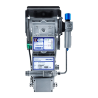
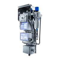
Operating manual VISATRON® Oil Mist Detector VN2020 / VN2020 EX
Part number 183001 Version 3.0
ASSEMBLY AND INSTALLATION
6 Assembly and installation
Failure to comply with the safety instructions may result in major damage to
property or the environment and in serious injury or death.
Familiarise yourself with the basic safety instructions before starting assembly.
Section 2.4 Basic safety instructions
Observe the environmental conditions for assembling the device
Section 3.4.4 Environmental conditions
6.1 Preparatory steps by the customer
For installation and operation of the oil mist detection system, the following
must be provided by the customer at the installation site:
a supply line for compressed air;
a supply line for the electrical power supply;
a supply line to transfer the signals of the relay contacts;
a bus line for CANopen communication (optional); and
a bus line for RS485 communication (optional) for Remote Indicator II or
for Modbus communication
For details, see Section 3.4.1. Mechanical interfaces (M)
For details, see Section 3.4.2. Electrical interfaces (E)
6.1.1 Establishing the compressed air supply
The compressed air supply must be provided by the customer and have a compressed
air quality according to SO 8573-1:2010 – 6-4-4 up to the pressure regulator unit or
installed at connection P1. The compressed air supply may vary between 2-14 bar for
optimum operation.
Mild to severe bruising when handling compressed air
Risk of injury from whipping of the compressed air hose line.
Before connecting the supply pressure, check the applied system pressure.
Section 3.4.3 Pneumatic interfaces (P)
6.1.2 Establishing the electrical power supply
The electrical power supply must be provided by the customer up to the measuring
head:
• Power supply: 18 Volt to 31.2 Volt DC, max. 2 A
• Nominal voltage: 24 Volt DC
 Loading...