Operating manual VISATRON® Oil Mist Detector VN2020 / VN2020 EX
Part number 183001 Version 3.0
ASSEMBLY AND INSTALLATION
6.4.2 Electrical installation of the terminal box for the VN2020 series
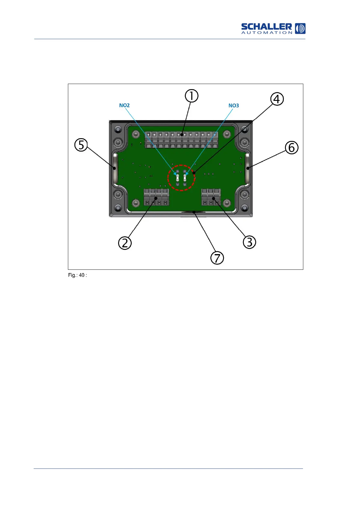
All the electrical terminal connections are on the connection board of the terminal box,
to which the bus and alarm supply lines and the power supply are connected, as shown
in the figure below.
Connection board, VN2020 terminal box
1: “Relay” terminal strip
2: “Power supply 24V” terminal strip
3: “Remote indicator”
terminal strip
4: Wire break resistors,
NO2/NO3
5: Cable entry, left
6: Cable entry, right
7: Cable entry, bottom
Required tools:
Cross-head screwdriver, drive PH 2
Slotted screwdriver, width 2.5 mm
The electrical installation of the terminal box is completed in a total of 6 steps:
Step 1: Remove cover of terminal box
Step 2: Select and install the wire break resistors according to the terminal box circuit
diagram
Step 3: Electrical connection of the relay contacts
Step 4: Electrical connection of the remote indicator (optional)
Step 5: Electrical connection of the power supply
Step 6: Electrical connection of the housing earthing
 Loading...