Planning the MOBY D system
4.1 Fundamentals of application planning
MOBY D
26 System Manual, 01/2010, J31069-D0147-A6-7618
6J
6D
$17'
/
0'6
0'6
63
/
7UDQVPLVVLRQ
ZLQGRZ
0HWDOSODWHVSDFHUNLW*7$%
6LGHYLHZ
3ODQYLHZ
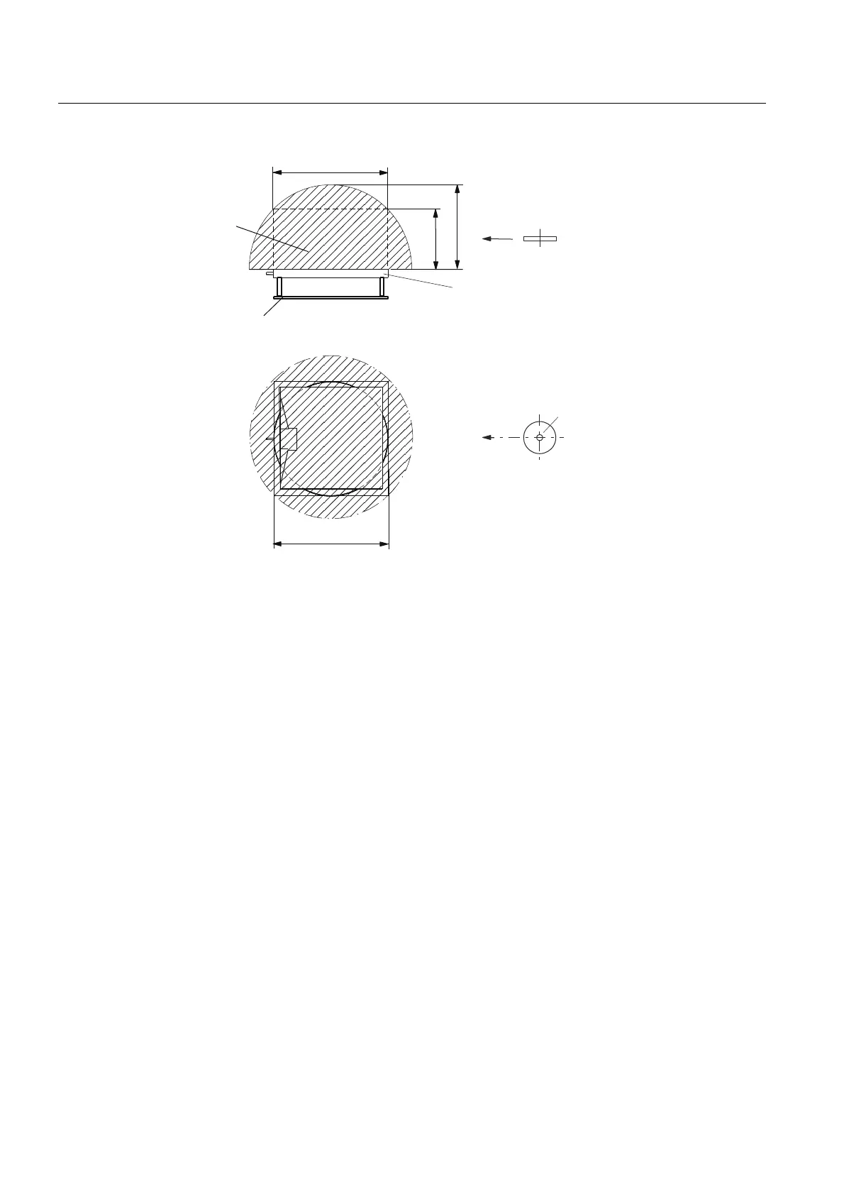
S
a
: Operating distance between MDS and SLG
S
g
Limit distance
(maximum clear distance between upper surface of antenna and MDS, at which the
transmission can still function under normal conditions)
L Length of the transmission window (300 mm)
SP Crossover point of the axes of symmetry of the MDS
Figure 4-1 Transmission window based on the example of ANT D5
The active field to the MDS comprises a circle (ANT D5) or a square (ANT D6, D10;
SLG D12/D12S). The MDS can be processed as soon as the crossover point (CP) of the
MDS enters the circle or square of the transmission window. The direction of movement and
rotation of the MDS has no effect.
From the diagrams above, it can also be seen that operation is possible within the area
between S
a
and S
g
. The active operating area reduces as the distance increases, and
shrinks to a single point at distance S
g
. Only static mode should thus be used in the area
between S
a
and S
g
.
For more detailed information on the transmission windows of the individual antennas, refer
to the respective antenna or SLG chapters.
 Loading...