Planning the MOBY D system
4.3 Installation guidelines
MOBY D
38 System Manual, 01/2010, J31069-D0147-A6-7618
4.3 Installation guidelines
4.3.1 Overview
The MDS and SLG are inductive devices. Any type of metal, in particular iron and
ferromagnetic materials, in the vicinity of these devices will affect their operation. Some
points need to be considered during planning and installation if the field data described in the
preceding chapter are to retain their validity:
● The use of permissible mounting material
● The minimum distance between two antennas
(see chapter "Antennas (Page 205)")
● The minimum distance between two adj
acent MDS
(see chapter "Mobile data storage units (Page 95)")
● The metal-free area for flush-mounting of SLGs in met
al
● Mounting of multiple antennas on metal frames or racks
The following sections describe the impact on the functionality of the MOBY D identification
system when mounted in the vicinity of metal.
4.3.2 Permissible mounting material
Securing SLG and antennas
In order to comply with UL guidelines, the components must only be secured with the fixing
materials described below.
The positions of the fixing holes for the device are shown in the
Dimension drawings
section.
Fixing to metal
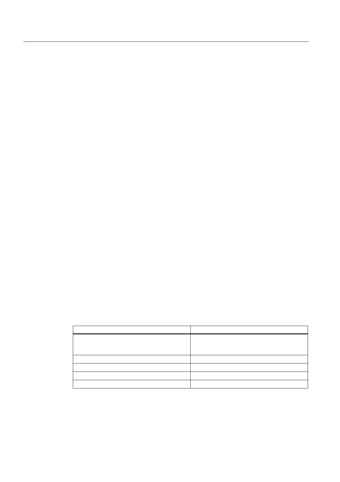
Table 4- 13 Fixing the SLG and antennas to metal
SLG/antenna Screw type
1
SLG D11, SLG D11S;
SLG D12, SLG D12S;
Antenna duplexer
M5 x 8, 8.8, DIN ISO 4017
SLG D10, SLG D10S M6 x 8, 8.8, DIN ISO 4017
Antenna ANT D5 M6 x 8, 8.8, DIN ISO 4017
ANT D6 antenna M6 x 8, 8.8, DIN ISO 4017
ANT D10 antenna M6 x 8, 8.8, DIN ISO 4017
1)
Represents minimum length
 Loading...