System integration
9.4 ASM 475
MOBY D
256 System Manual, 01/2010, J31069-D0147-A6-7618
9.4.4 Configuration
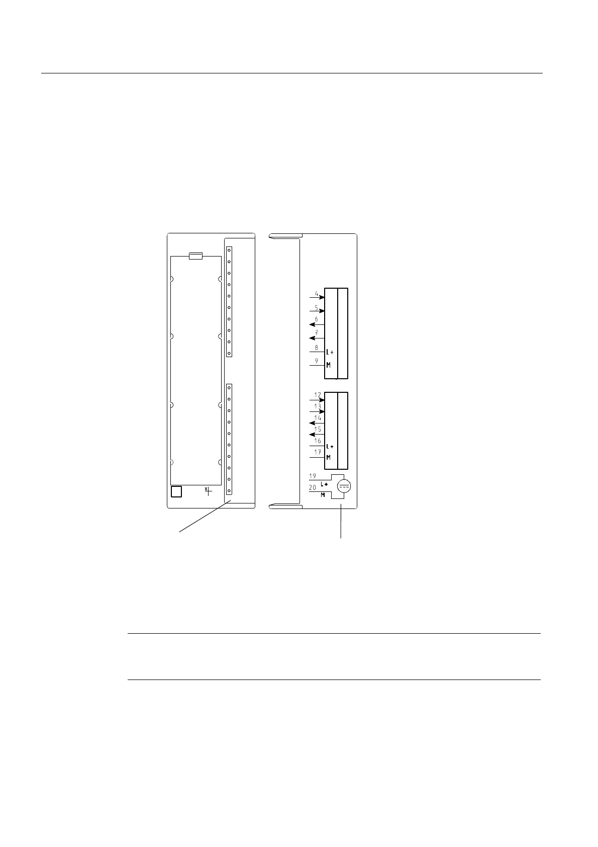
Front panel
The figure below illustrates the bezel of the ASM 475 and the inside of the front door
complete with the associated connection diagram. The write/read devices must be
connected to the ASM in accordance with the connection diagram.
6WDWXVDQGHUURUGLVSOD\V &RQQHFWLRQGLDJUDP
7KHQXPEHUVRIWKH
FRQQHFWLRQVUHIHUWR
&RQQHFWRU;RIWKH
WRSHQFORVXUHVHFWLRQ
$60
02%<
6/*b
6
6
(
(
6
6
(
(
6)
9'&
$&7B
(55B
35(B
5['B
$&7B
(55B
35(B
5['B
6/*b
*7b*$
Figure 9-18 Bezel and inside of the front door of the ASM 475
Note
With MOBY D, the SLG power supply cannot be connected through the ASM (exception:
SLG D12S (plug-in version)).
 Loading...