Planning the MOBY D system
4.6 MOBY shield concept
MOBY D
84 System Manual, 01/2010, J31069-D0147-A6-7618
Configuration of an S7-300 with MOBY
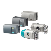
When the SLG is connected to ASM 475, the cable shield must be connected to a shield
terminal. Shield terminals and holding clips are standard components of the product
spectrum of S7-300.
7HUPLQDOHOHPHQW
+ROGLQJFOLS
&DEOHWR6/*
&DEOHWR6/*
Figure 4-34 Configuration of ASM 475 with shield connecting element
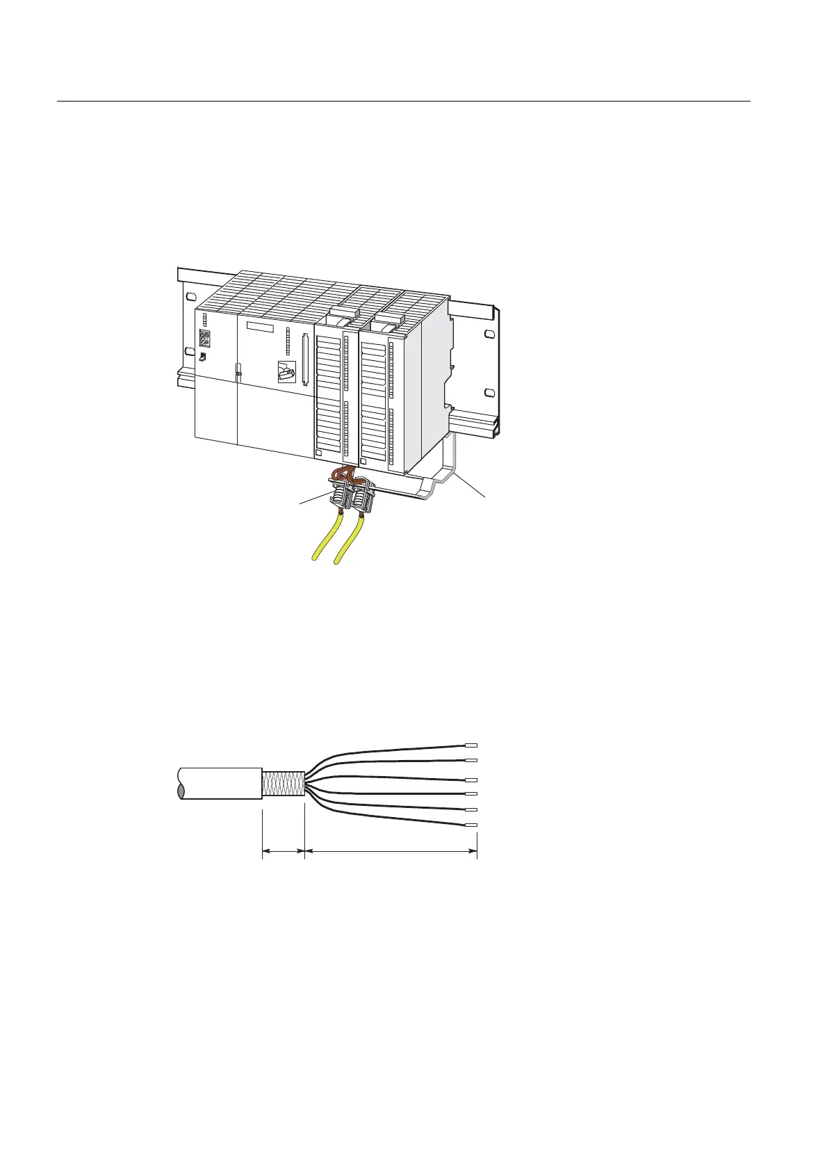
Cable assembly for ASM 475
To achieve electromagnetic compatibility, the SLG cable must be routed via an S7-300
shield connecting element (see previous diagram). The cable shield should be exposed as
shown in the diagram below.
'LPHQVLRQVLQPP
Figure 4-35 Exposure of the cable shield
 Loading...