06.2005 Engineering Information
Siemens AG 6SE7087-6QX70 (Version AE)
SIMOVERT MASTERDRIVES Compendium Motion Control 11-3
11.2 Specification of the travel curve
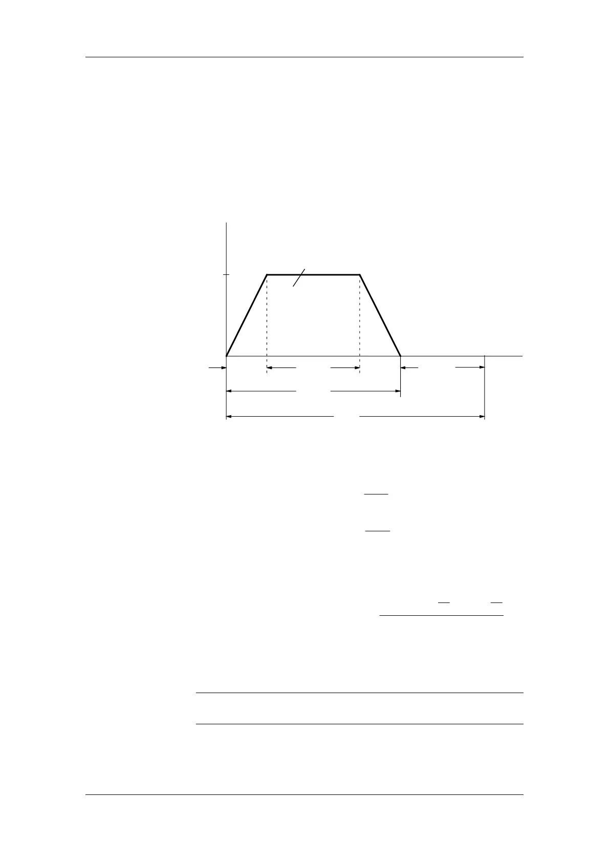
The travel curve - namely the v,t diagram when a linear drive is being
used - is determined from the information relating to travel distances,
maximum speed, acceleration, deceleration and the cycle time. If multi-
axis drives are used, the interdependence of the individual travel curves
must be taken into account. The travel curve is needed for deciding on
the thermal rating of the motor and the type of braking resistors. It
should therefore represent a "worst-case scenario" for the particular
type of motor and resistors chosen.
ttt
t
bv
tot
k
v
max
Area represents distance s
tot
v
t
t
p
T
Fig. 11-1 Example of a simple travel curve
♦ Acceleration (b) time [s]
t
v
a
b
b
=
max
♦ Deceleration (
v) time [s] t
v
a
v
v
=
max
v
max
Maximum speed [m/s]
a
b,v
Acceleration, deceleration [m/s
2
]
♦ Time for constant (
k) travel [s] t
sv
t
v
t
v
k
tot
b
v
=
−⋅−⋅
max max
max
22
s
tot
Travel distance [m]
♦ Travel time [s]
tttt
tot b k v
=++
On rotating drives (turning mechanisms), the values ω
max
, α
b,v
, ϕ
tot
have to be applied instead of v
max
, a
b,v
, s
tot
.
NOTE
 Loading...


