Functions
6-52 7SJ62 Manual
C53000-G1140-C121-1
Interaction with
Automatic
Reclosing
Equipment
At address DFWLYH, it can be specified whether or not the 67-2 elements
should be supervised by the status of internal or external automatic reclosing device.
If address is set to :LWK$FWLYH, the 67-2 elements will not operate unless
automatic reclosing is enabled. If address is set to $OZD\V, the 67-2 elements
will always operate.
When reclosing occurs, it is desirable to have high speed protection against temporary
faults. With address set to :LWK$FWLYH, the 67-2 elements may be set for
high speed tripping. If the fault still exists after the first reclose, the 67-2 elements can
be blocked and the 67-1 and/or 67-TOC elements will provide time delay tripping. For
those situations where reclosing is disabled, the 67-2 elements are blocked and the
67-1 and/or 67-TOC elements provide time delay tripping. In summary, setting ad-
dress to :LWK $FWLYH defeats one-shot, high-speed tripping via the 67-2
element for those situations where automatic reclosing is disabled.
When an external automatic reclosing device is utilized, a signal indicating that the de-
vice is enabled must be transmitted to the 7SJ62 relay via a binary input.
Direction Limit Line
and Directional
Orientation
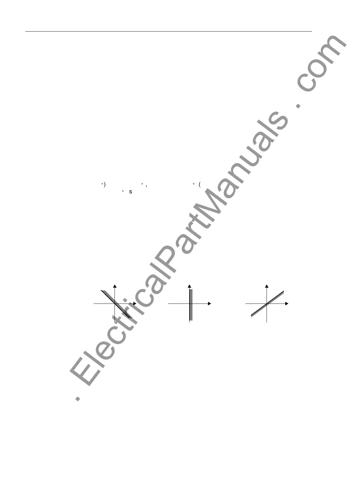
At address 1RUPDO/RDG, the directional limit line may be set as inductive
(135
), resistive (90
), or capacitive (45
) (see Figure 6-27). As a rule, the option in-
ductive (135
) is used since power system elements are inductive by nature.
The directional orientation may be established at address 'LUHFWLRQ. Di-
rectional overcurrent protection normally operates in the direction of the facility to be
protected (line, transformer, etc.). If the device is properly connected in accordance
with one of the circuit diagrams in Appendix A3, this is the
forward
direction.
If the voltage used to determine fault direction drops below the minimum value, record-
ed voltage values are available from a buffer based on the last two cycles of sufficient
voltage. If recorded voltage is not available due to closing in on a fault, tripping will take
place without directional determination.
Figure 6-27 Definition of the Directional Limit Line (addresses and )
User Specified
Curves
If address 72& was set to 8VHU'HILQHG3LFNXS &XUYH or 8VHU
'HILQHG3LFNXSDQG5HVW&XUYH during configuration of the user-specified
curve option, a maximum of 20 value pairs (current and time) may be entered at ad-
dress to represent the time-current characteristic curve associated with the 67-
TOC element. This option allows point-by-point entry of any desired curve.
If address was set to 8VHU'HILQHG3LFNXSDQG5HVHW&XUYH during
configuration of the user-specified curve option, additional value pairs (current and re-
set time) may be entered at address 0RI385HV77S to represent the reset
curve associated with the 67-TOC element.
Current and time values are entered as multiples of the address and set-
tings. Therefore, it is recommended that addresses and be initially set to
R
jX
,1'8&7,9(
R
jX
5(6,67,9(
R
jX
&$3$&,7,9(
www . ElectricalPartManuals . com
 Loading...


