Functions
6-537SJ62 Manual
C53000-G1140-C121-1
1.00 to simplify the calculation of these ratios. Once the curve is entered, the settings
at addresses and may be modified if necessary.
Upon delivery of the device, all time values are set at ∞, preventing pickup of the de-
vice from initiating a trip signal.
When entering a user-specified curve, the following must be observed:
− The value pairs should be entered in increasing sequence. As few as 10 pairs of
numbers may be entered at the user’s option. Each unused pair must then be
marked as unused by entering “∞“ for the time and current values. It is important to
view the curve to ensure that it is clear and constant.
− Current flows which are less than the smallest current value entered will not lead to
an extension of the tripping time beyond the time associated with this smallest cur-
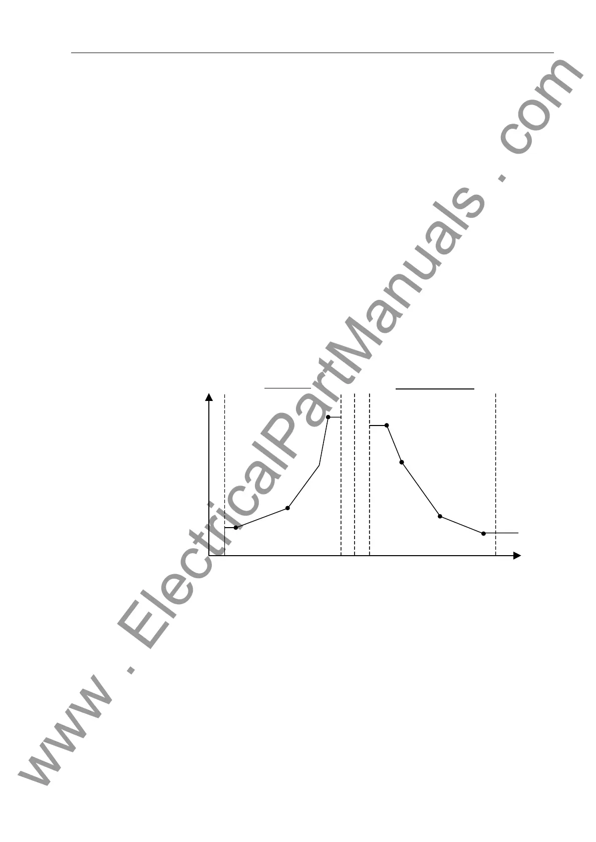
rent value entered. The characteristic curve (see Figure 6-28) represents constant
tripping time for currents less than the smallest current value entered.
− Current flows which are greater than the largest current value entered will not lead
to a reduction of the tripping time below the time associated with the largest current
value entered. The characteristic curve (see Figure 6-28) represents constant trip-
ping time for currents greater than the largest current value entered.
The time and current value pairs are entered at address to recreate the drop-
down curve. The following must be observed:
Figure 6-28 Use of a User-Specified Curve
− Current flows which are greater than the largest current value entered will not lead
to an extension of the reset time beyond the time associated with the largest current
value entered. The reset curve (see Figure 6-28) represents constant reset time for
currents larger than the largest current value entered.
− Current flows which are less than the smallest current value entered will not lead to
a reduction of the reset time below the time associated with the smallest current val-
ue entered. The reset curve (see Figure 6-28) represents constant reset time for
currents smaller than the smallest current value entered.
− Current flows less than 0.05 * 67-TOC pickup setting will cause immediate reset.
0.05
0.9 1
1.1
20
t
I
Largest Current Point
Smallest Current Point
Smallest Current Point
Largest Current Point
Reset Curve
Characteristic Curve
www . ElectricalPartManuals . com
 Loading...


