AUTOMATIC TRANSMISSION (4 A/T) 7B1-25
Table B-4 : “POWER” Light Circuit Check (“POWER” Light Comes ON
Steadily)
WIRING DIAGRAM
Refer to “TABLE B-3” in this section.
TROUBLESHOOTING
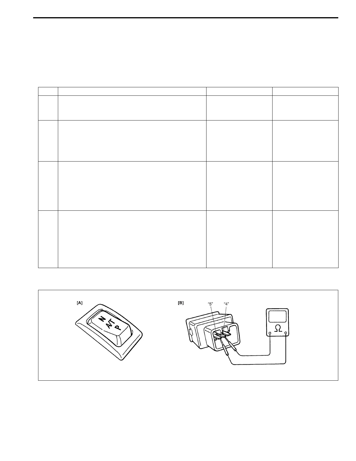
[A] for Step 1/[B] for Step 4
Step Action Yes No
1 Check Power/Normal change switch position.
Is switch button at Normal position?
Go to Step 2. Set Power/Normal
change switch at Nor-
mal position.
2 Check lamp circuit for short.
1) Turn ignition switch OFF and disconnect PCM
connectors.
2) Turn ignition switch ON.
Does “POWER” lamp come ON steadily?
“GRY/BLU” circuit
shorted to ground.
Go to Step 3.
3 Check Power/Normal change switch circuit.
1) Check resistance between terminal E61-31 of dis-
connected PCM connector and body ground with
P/N change switch OFF.
Is continuity indicated?
Go to Step 4. Check PCM ground
circuit for open.
If ground circuit is OK,
substitute a known-
good PCM and
recheck.
4 Check Power/Normal change switch for operation.
1) Remove Power/Normal change switch.
2) Check continuity between switch terminals “4” and
“5” under each condition below.
Normal position: No continuity
Power position: Continuity.
Is check result satisfactory?
“ORN/BLU” circuit
shorted to ground.
Replace Power/Normal
change switch.

 Loading...


