DISASSEMBLY AND ASSEMBLY
TRAVEL SYSTEM
1
4
TRAVEL SYSTEM 4C0AX00
TRAVEL SYSTEM
Removing the crawler
Important: When replacing crawlers, replace both the
right and left ones at the same time.
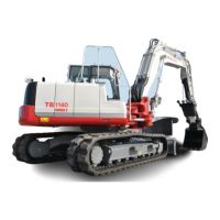
1. Lift up the machine.
• Use the blade and hoe attachment to raise the
machine.
2. Loosen the crawler tension for the crawler (1).
• When loosening the check valve (2), do it slowly.
Stop loosening the check valve once grease
starts to come out.
If no grease comes out, slightly move the machine
forward and backward.
Check valve: 177 N·m (130.5 ft.-lb)
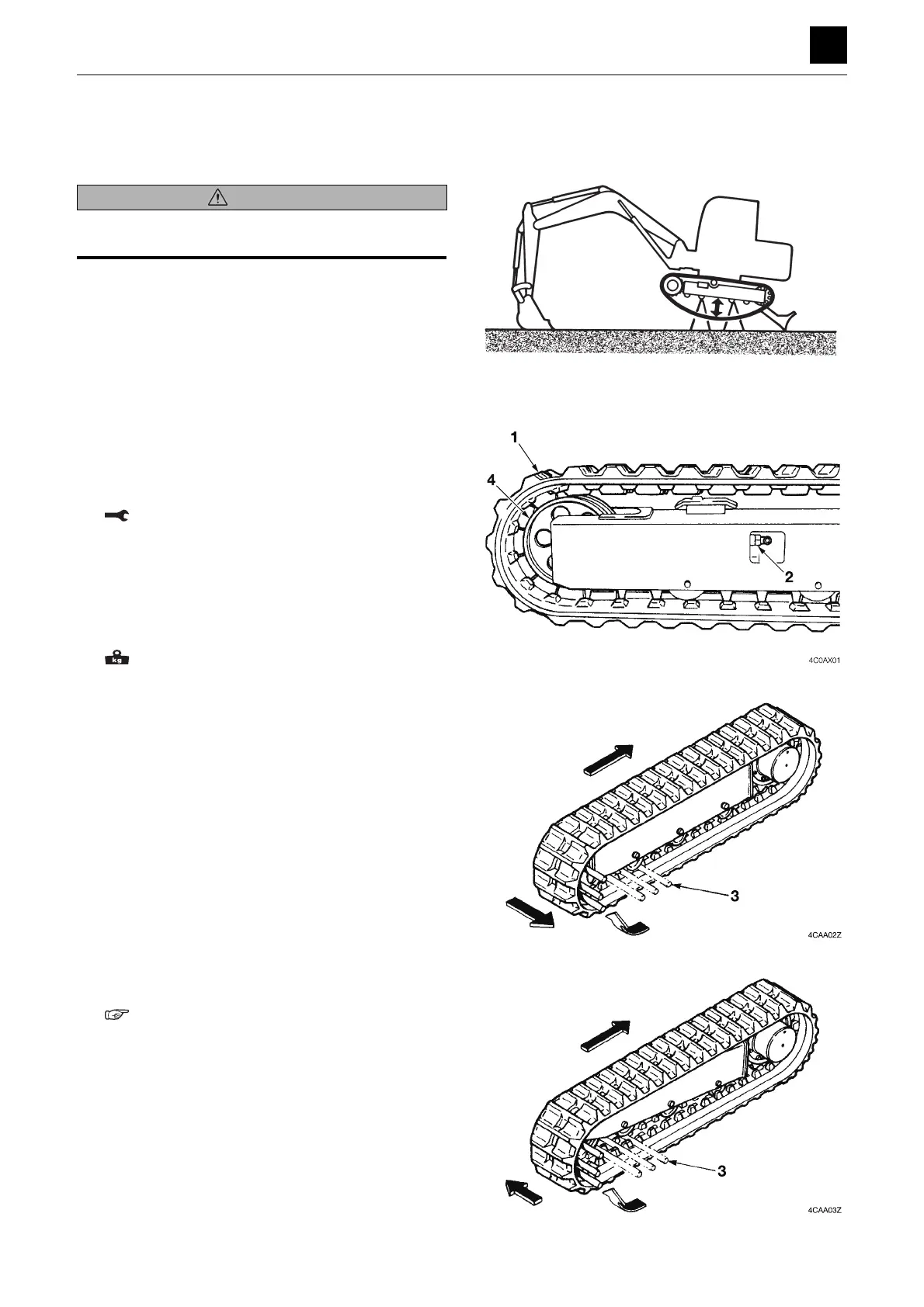
3. Insert the iron pipe (3) into the crawler and then ro-
tate the sprocket in the reverse direction.
4. Stop rotating the sprocket once the pipe reaches the
side of the idler.
5. Slide the crawler over to the side and remove it.
Rubber crawler (One side): 55 kg (120 lb)
Installing the crawler
1. Lift up the machine, and insert the crawler into the
frame.
• Set the crawler so that it is engaged with the
sprocket.
2. Insert the iron pipe (3) into the crawler and then ro-
tate the sprocket in the reverse direction.
3. Stop rotating the sprocket once the pipe (3) reaches
the side of the sprocket.
4. Slide the crawler into a position where it can be prop-
erly fitted to engage with the idler.
5. Position the crawler so as to ensure that it is securely
engaged with the sprocket and idler and then adjust
the crawler tension.
“2. Service data, Performance criteria”
WARNING
When working under the machine while it is raised up, be
sure to use a stand to support the machine.
4C0AQ01Z
 Loading...