FUNCTION
PROPORTIONAL CONTROL SOLENOID VALVE (2ND AUXILIARY LINE PIPING)
1
3
PROPORTIONAL CONTROL SOLENOID VALVE
(2ND AUXILIARY LINE PIPING)
3K4AX00
PROPORTIONAL CONTROL SOLENOID VALVE
(2ND AUXILIARY LINE PIPING)
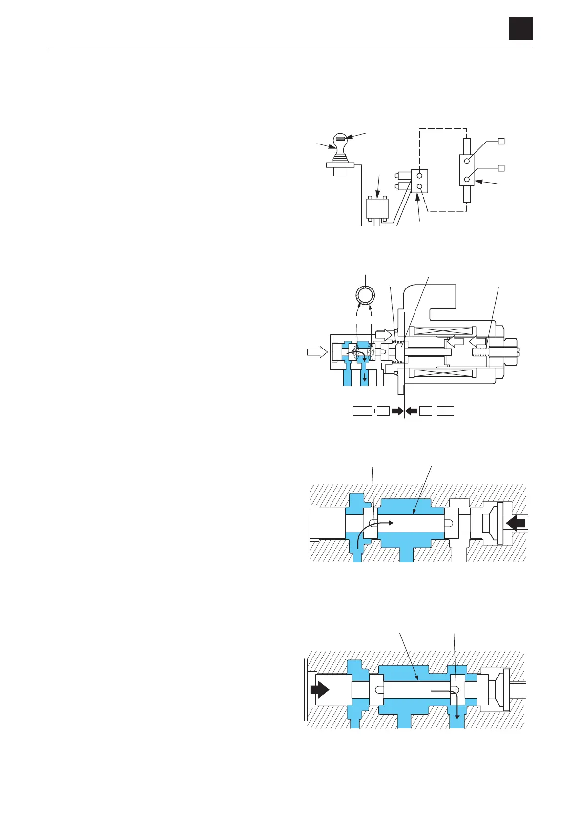
The proportional lever (2) and proportional amplifier (3)
of the pilot valve (1) control the driving current that flows
to the proportional control solenoid valve (4), which con-
trols the pilot pressure of the control valve (5) (auxiliary
section) whereby the flow rate of the auxiliary line piping
changes.
The proportional control solenoid valve controls the sec-
ondary pressure using the built-in proportional pressure-
educing valve. The secondary pressure generated cor-
responds to the changes in current because of the force
used to generate the secondary pressure being applied
to the solenoid in accordance with the amount of current
flowing through the coil.
When current flows through the solenoid, a thrust force
proportional to the current is generated and moves the
spool (6) so that the oil supplied from the port P is intro-
duced into the port A on the secondary pressure side,
which increases the pressure Pa of the port A.
The pressure Pa acts on the differential area S between
the cross section A1 and cross section B1 of the spool
(6), and the spool (6) is pushed to the solenoid side by
the oil pressure, Pa × s. The spool (6) stops at the posi-
tion where the sum of the oil pressure, Pa × s, and the
force, Fk, exerted by the springs (7) is balanced with the
thrust force, Fs, generated by the solenoid. The weight,
Fks, of the spring (8) used for fine adjustment of the sec-
ondary pressure acts in the direction (left) of assistance
of the thrust force from the solenoid.
When the thrust force is greater than a set value, the
spool (6) is moved to the left, which connects the port P
(supply side) and the port A (secondary side) together
through the notch (9).
When the thrust force is lower than a set value, the spool
(6) is moved to the right, which connects the port A (sec-
ondary side) and the port T (tank side) together through
the notch (10).
The opening areas of the notch (9) on the supply side
and the notch (10) on the discharge side are thus con-
trolled by the movement of the spool (6), and a second-
ary (pilot) pressure can be provided that corresponds to
the thrust force generated by the solenoid.
3K4AQ01Z
2
3
1
4
5
6
7
8
S=A1-B1
S
Paxs
Paxs Fk Fs Fks
B1 A1
AP T
Fs Fks
Fk
3K4AQ02Z
A TP
69
3K4AQ03Z
3K4AQ04Z
A TP
6 10
 Loading...